Supercharge Your Innovation With Domain-Expert AI Agents!

A pressure sensor circuit and its debugging method

A technology of pressure sensor and voltage amplifying circuit, which is applied in the field of pressure sensor circuit and its debugging, which can solve the problems of output signal reduction, bridge output signal circuit noise sensitivity, instability, etc., achieves low static consumption current and meets debugging requirements , the effect of good stability

Active Publication Date: 2019-10-15
WUHAN AVIATION INSTR
View PDF6 Cites 0 Cited by
  • Summary
  • Abstract
  • Description
  • Claims
  • Application Information

AI Technical Summary

Problems solved by technology

The salient features of the pressure-sensitive core sensitive bridge of these principles are: 1) low sensitivity, usually the full-scale output is only 1mV / V ~ 3mV / V; 2) the bridge arm resistance of the sensitive bridge is usually 2.5kΩ to 5kΩ
The pressure sensor based on the principle of sputtering film pressure sensitivity or sapphire pressure sensitivity needs to realize the design requirements of the two-wire 4mA ~ 20mA output, there is the following contradiction: in order to reduce the static consumption current of the pressure sensor circuit, the circuit needs to use low consumption current At the same time, the power supply voltage of the sensitive bridge should be reduced as much as possible; but when the power supply voltage of the sensitive bridge is reduced, the output signal will decrease accordingly. In order to realize the 4mA~20mA current signal output, it is necessary to increase the amplification factor of the circuit. The magnification usually needs to reach 1000 times or even higher
When the magnification is increased, the bridge output signal becomes more sensitive to weak circuit noise, resulting in output jumps and instability, which cannot meet the design requirements of the pressure sensor

Method used


Image

  • A pressure sensor circuit and its debugging method
  • A pressure sensor circuit and its debugging method

Examples


Embodiment

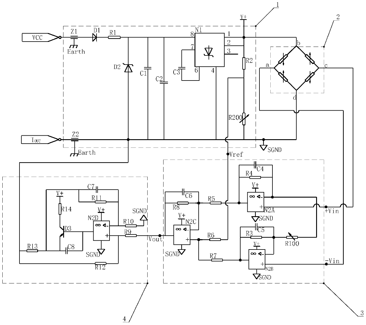
[0059] Such as figure 2 As shown, the sensitive bridge 2 is a sputtered thin-film pressure sensitive bridge with an output sensitivity of 1.5mV, the minimum bridge resistance of the sensitive bridge is 3.2kΩ, and the minimum zero output voltage is 0.1mV. The implementation steps are as follows:

[0060] Step 1. Select a low-power precision device op amp and voltage reference:

[0061] according to figure 1 The circuit selects the main low-power precision devices as operational amplifiers and voltage references.

[0062] The selection condition of operational amplifier is: low static consumption current: the maximum static consumption current summation of described operational amplifier N2A, N2B, N2C and N2D four operational amplifiers is I 1 , then there should be I 1 ≤1.5mA; allow normal operation under single power supply, low voltage input conditions; output voltage amplitude as close as possible to the working power supply voltage, especially for rail-to-rail operation...


PUM


Abstract

The invention belongs to the pressure sensing technology and provides a pressure transducer circuit and a commissioning method thereof. The pressure transducer circuit comprises four parts including a circuit voltage reference circuit (1), a sensitive electrical bridge (2), a voltage amplifier circuit (3) and a current conversion circuit (4). The pressure transducer circuit, by reasonably selecting voltage reference, operational amplifier and other mainly devices, reduces supply voltage of a Wheatstone pressure sensitive electrical bridge and increases the resistance of a zero voltage dividing adjusting resistor, so that the static consumption current of the transducer signal conditioning circuit is no greater than 3.8mA, and the commissioning requirement of the pressure transducer is satisfied. High magnification of weak signals of a pressure sensitive electrical bridge is realized through reasonably determining the amplification times of a three op-amp instrumentation amplification circuit and the capacity of parallel porcelain capacitors on a negative feedback resistor of a voltage amplifier circuit, and the circuit is provided with excellent stability.

Description

technical field [0001] The invention belongs to pressure sensing technology, and relates to a pressure sensor circuit and a debugging method thereof. Background technique [0002] The pressure sensor adopts a two-wire 4mA~20mA standard current loop design, which can realize the long-distance transmission of electrical signals, and has the advantages of accurate signal transmission, strong anti-interference ability, and low static current consumption; at the same time, the two-wire design can effectively reduce pressure sensors. Number of electrical connection cables to and from the system. The pressure sensor with two-wire 4mA~20mA output must require that the static consumption current of the pressure sensor circuit should be less than 3.8mA, otherwise it cannot be debugged. [0003] The pressure sensor often adopts the pressure sensitive core of the sputtering film pressure sensitive principle or the titanium / silicon-sapphire pressure sensitive principle. The above sensit...

Claims


Application Information

Patent Timeline
Patent Type & Authority Patents(China)
IPC IPC(8): G01L1/22
Inventor 徐阳辉樊佩生王辉
Owner WUHAN AVIATION INSTR
Features
  • R&D
  • Intellectual Property
  • Life Sciences
  • Materials
  • Tech Scout
  • Unparalleled Data Quality
  • Higher Quality Content
  • 60% Fewer Hallucinations
Learn More