
Method for controlling dimming signal and device and system thereof

A dimming signal and brightness signal technology, which is applied in the field of LED backlight LCD TVs, can solve the problems that the backlight drive control signal cannot be synchronized with the brightness signal of the LCD screen, cannot improve image quality, and has adverse effects on images, etc.

Active Publication Date: 2016-09-28
SHENZHEN SKYWORTH RGB ELECTRONICS CO LTD
View PDF5 Cites 11 Cited by
  • Summary
  • Abstract
  • Description
  • Claims
  • Application Information

AI Technical Summary

Problems solved by technology

The use of edge-lit regional dimming backlights can meet the requirements of TVs with HDR functions. At present, the edge-lit regional dimming in the industry usually uses the main chip of the TV motherboard to generate dynamic regional dimming signals, and then controls the regional dimming to drive constant current. board, the backlight drive control signal generated in this way cannot be synchronized with the brightness signal of the LCD screen, especially for the image signal of a TV with HDR function, which will lead to the appearance of smears, shadows and water ripples. The quality of the image, on the contrary, has a negative impact on the image

Method used


Image

  • Method for controlling dimming signal and device and system thereof
  • Method for controlling dimming signal and device and system thereof
  • Method for controlling dimming signal and device and system thereof

Examples


Embodiment Construction

[0056] The embodiments of the present invention will be further described in detail below in conjunction with the drawings and embodiments. It should be understood that the specific embodiments described here are only used to explain the embodiments of the present invention, rather than to limit the embodiments of the present invention. In addition, it should be noted that, for the convenience of description, the drawings only show some but not all structures related to the embodiments of the present invention.

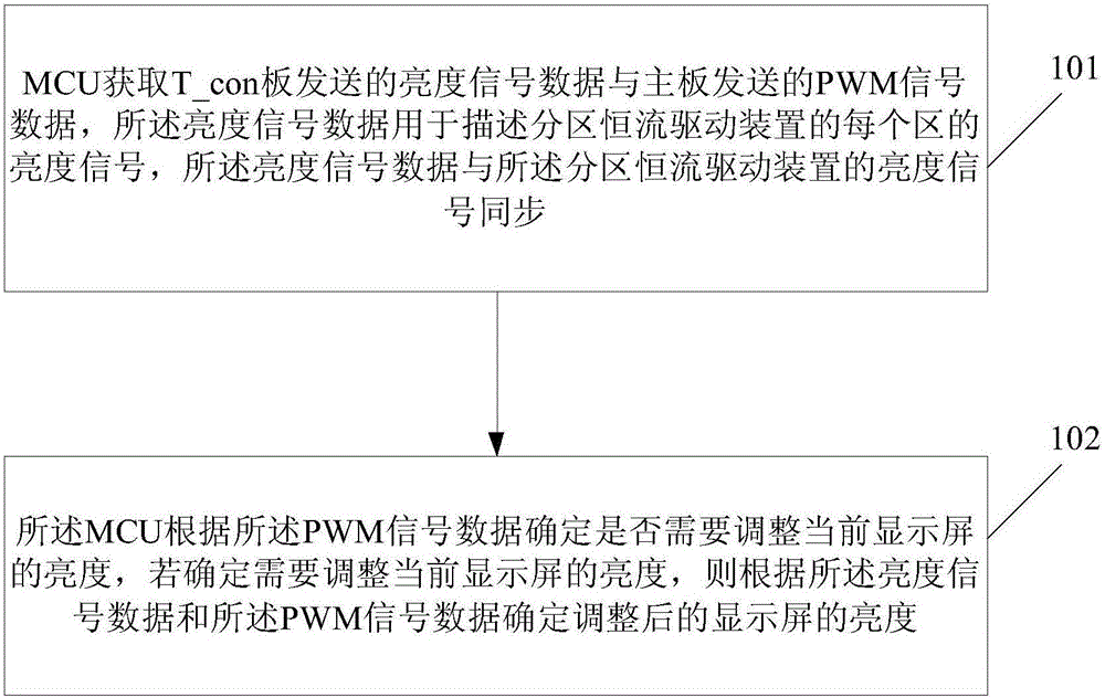
[0057] refer to figure 1 , figure 1 It is a schematic flowchart of a method for controlling a dimming signal provided by an embodiment of the present invention.

[0058] like figure 1 As shown, the method for controlling the dimming signal includes:

[0059] Step 101, the microcontroller unit (Microcontroller Unit, MCU) acquires the brightness signal data sent by the T_con board and the pulse width modulation (Pulse Width Modulation, PWM) signal data sent by the m...


PUM


Abstract

The invention discloses a method for controlling a dimming signal and a device and a system thereof The method comprises the steps that an MCU acquires brightness data transmitted by a T_con board and PWM signal data transmitted by a mainboard; and the MCU determines adjustment of the current brightness of a display screen according to the PWM signal data, and the adjusted brightness of the display screen is determined according to the brightness signal data and the PWM signal data if the requirement for adjusting the current brightness of the display screen is determined. According to the method, the requirements of LED liquid crystal backlight televisions of different sizes and different lamp areas can be met, the requirements for the frame quality of the televisions having an HDR function can be met, and the problems of trailing, ghosting and water ripple of images can be solved; the contrast and the depth of field of the images can be enhanced, the visual perception of consumers can be enhanced and the development of the liquid crystal televisions can be promoted; and partitioning control of liquid crystal television LED lamps can be realized, power consumption of the televisions can be reduced and thus the method is energy-saving and environment-friendly.

Description

technical field [0001] Embodiments of the present invention relate to LED backlight liquid crystal televisions, and in particular to a method, device and system for controlling dimming signals. Background technique [0002] With the development of smart TVs, consumers have higher and higher requirements for image quality, and TVs with high-dynamic range (High-Dynamic Range, HDR) functions have higher requirements for image quality, such as TVs with HDR functions The TV requires the local brightness of the image to be brighter and the darkness darker to increase the ratio. The use of edge-lit regional dimming backlights can meet the requirements of TVs with HDR functions. At present, the edge-lit regional dimming in the industry usually uses the main chip of the TV motherboard to generate dynamic regional dimming signals, and then controls the regional dimming to drive constant current. board, the backlight drive control signal generated in this way cannot be synchronized wi...

Claims


Application Information

Patent Timeline
IPC IPC(8): G09G3/34G09G5/10
CPCG09G3/3406G09G5/10
Inventor 巢铁牛李德盛戴奇峰
Owner SHENZHEN SKYWORTH RGB ELECTRONICS CO LTD
Learn More