No-pollution waste and old wire recovery device

A recovery device and non-polluting technology, which is applied in the field of waste wire recovery devices, can solve problems such as air pollution, waste of resources, metal surface oxidation, etc., and achieve the effects of reducing environmental pollution, facilitating reuse, and reducing oxidation

Active Publication Date: 2016-09-28
黎清弟
View PDF3 Cites 11 Cited by
  • Summary
  • Abstract
  • Description
  • Claims
  • Application Information

AI Technical Summary

Problems solved by technology

[0002] When a short circuit occurs in the line, the plastic skin wrapped around the waste wire will stick to the outside of the metal wire core due to heat, and cannot be separated conventionally. The existing treatment method of burning will cause great air pollution, and the metal

Method used


Image

  • No-pollution waste and old wire recovery device
  • No-pollution waste and old wire recovery device
  • No-pollution waste and old wire recovery device

Examples


Embodiment 1

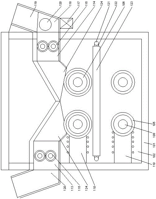
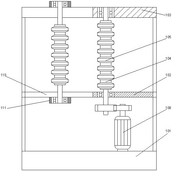
[0026] like Figure 1-4 As shown, a pollution-free waste wire recovery device includes a support 101 and a wire core stripping device and a crushing and separating device arranged on the support. A bottom plate 102 is arranged on the support, and a The top plate 103, the core stripping device and the crushing and separating device are both located between the bottom plate and the top plate;

[0027] The wire core stripping device includes a wire core separation device and a wire core cutting device, and the wire core separation device includes a first roller set 104 arranged between the top plate and the bottom plate and arranged on the The first driving device 108 below the bottom plate, the first roller set includes two rollers arranged parallel to each other, and a cable conveying cavity for conveying cables is formed between the two rollers , the first driving device is used to drive one of the rollers to rotate;

[0028] The wire core cutting device includes a second ro...

Embodiment 2

[0033] In this embodiment, on the basis of Embodiment 1, preferably, the second crushing chamber is used for crushing the plastic cortex. In this embodiment, an output channel 118 is provided below the second crushing chamber. A blower 117 is arranged on one side of the passage, a plastic skin passage 119 is arranged on the side of the output passage away from the blower, and a metal channel connected to it is provided below the output passage near the side of the blower. Particle channel 120 .

[0034] By using a blower, under the action of the blower, due to the different weights of the metal core and the plastic cortex, under the action of the wind, the lighter plastic cortex is output through the plastic sheath channel, and the heavier metal core particles pass through the metal particle channel output.

Embodiment 3

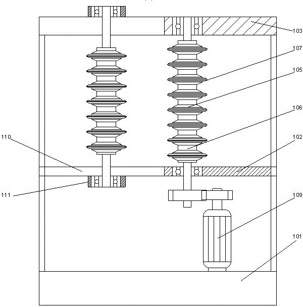
[0036] On the basis of Embodiment 1, this embodiment discloses a preferred structure of the first roller set. Preferably, two roller outer walls of the first roller set are respectively provided with convex The flange structure 105 is arranged along the outer walls of the two rollers at equal intervals in the circumferential direction, and the flange structures on the two rollers are alternately arranged. By adopting the flange structure, it forms a crest and trough structure on the roller surface of the first roller set, so that when the waste wire passes through the cable conveying cavity formed by the flange structure, it will not move down due to gravity, In this way, it is convenient for it to be squeezed under concentrated force, and it can also prevent the waste wire from being unable to be transported to the second roller set, and the conveying track of the waste wire is limited, which helps to improve the cutting efficiency.

[0037] In this embodiment, it is further ...


PUM


Abstract

The invention discloses a no-pollution waste and old wire recovery device, and the device comprises a support, a wire core peeling apparatus and a smashing separation apparatus, wherein the wire core peeling apparatus and the smashing separation apparatus are disposed on the support. The support is also provided with a bottom plate, and the top of the support is provided with a top plate. The wire core peeling apparatus and the smashing separation apparatus are respectively located between the bottom plate and the top plate. The wire core peeling apparatus comprises a wire core separation apparatus and a wire core cutting apparatus. The wire core separation apparatus comprises a first roller group disposed between the top plate and the bottom plate, and a first drive apparatus disposed below the bottom plate. The first roller group comprises two parallel rollers, and the two parallel rollers form a cable conveying cavity for conveying a cable. The first drive apparatus is used for driving one roller to rotate. According to the invention, the device employs the wire core peeling apparatus and the smashing separation apparatus, achieves the peeling and smashing of a plastic wire, and achieves the reuse of the plastic skin and a metal wire core.

Description

technical field [0001] The invention relates to a pollution-free recycling device for waste wires. Background technique [0002] When a short circuit occurs in the line, the plastic skin wrapped around the waste wire will stick to the outside of the metal wire core due to heat, and cannot be separated conventionally. The existing treatment method of burning will cause great air pollution, and the metal A large amount of non-metallic materials will adhere to the surface of the wire. During the combustion process, the metal surface will be severely oxidized, affecting the quality of the metal core, wasting a lot of resources, and greatly increasing the cost of wire recycling. Contents of the invention [0003] The purpose of the present invention is to provide a pollution-free waste wire recovery device, which can improve the problems existing in the prior art. By adopting the wire core stripping device and the crushing and separating device, the stripping and crushing opera...

Claims


Application Information

Patent Timeline
IPC IPC(8): H01B15/00
CPCH01B15/005Y02W30/82
Inventor 孙立民国际昌
Owner 黎清弟
Why Eureka
Try Eureka