Microstrip array antenna with harmonic suppression function

A technology of microstrip array and harmonic suppression, applied in the direction of antenna, antenna array, antenna grounding switch structure connection, etc., can solve the problems of large receiving antenna, difficult integration, serious secondary radiation, etc., achieve small size and improve performance , low cost effect

Active Publication Date: 2016-09-28
UNIV OF ELECTRONICS SCI & TECH OF CHINA
View PDF4 Cites 5 Cited by
  • Summary
  • Abstract
  • Description
  • Claims
  • Application Information

AI Technical Summary

Problems solved by technology

[0005] The purpose of the present invention is to propose a microstrip array antenna with harmonic suppression function, which overcomes the s...

Method used


Image

  • Microstrip array antenna with harmonic suppression function
  • Microstrip array antenna with harmonic suppression function
  • Microstrip array antenna with harmonic suppression function

Examples


Embodiment Construction

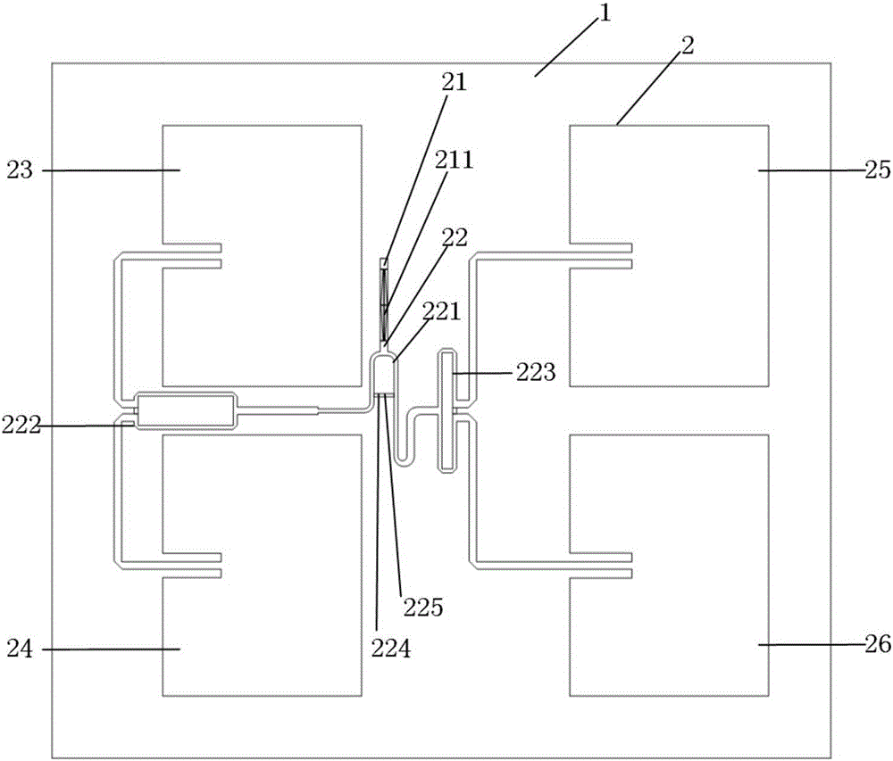
[0015] The present invention will be further described below in conjunction with accompanying drawing and specific embodiment: figure 1 As shown, a microstrip array antenna with harmonic suppression function includes a dielectric substrate and a microstrip array antenna 2 printed on the surface of the dielectric substrate 1 . The dielectric substrate 1 is an RF35 dielectric substrate with a thickness of 0.5mm, a dielectric constant of 3.5, a loss tangent of 0.0018, and a copper layer thickness of 0.018mm, with a size of 145*110mm. The microstrip array antenna 2 includes a microstrip feeder 21, a quarter power splitter 22, a first microstrip patch antenna 23, a second microstrip patch antenna 24, a third microstrip patch antenna 25 and a fourth microstrip patch antenna. Patch antenna 26, the patch antenna works at 2.45GHz, the size is 32*42mm, the microstrip feeder is inserted into the patch feed, the insertion depth is 10mm, and the slot width of the patch is 4mm. The 1 / 4 pow...


PUM


Abstract

The invention discloses a microstrip array antenna with a harmonic suppression function. The microstrip array antenna comprises a dielectric substrate and a microstrip antenna array printed on the surface of the dielectric substrate. According to the microstrip array antenna, feeding is carried out through microstrip lines loaded with compact microstrip resonant units, so that the harmonic radiation loss of the antenna can be avoided; and a miniaturization high-isolation power divider is adopted, so that the microstrip array antenna can be small in size and compact in structure. The microstrip array antenna of the invention can be used to a microwave power transmission system. The microstrip array antenna has the advantages of applicability to the plane miniaturization of a system, small size, easiness in integration and high efficiency.

Description

technical field [0001] The invention belongs to the field of antenna design, in particular to a microstrip array antenna with harmonic suppression function. Background technique [0002] With the increasing shortage of non-renewable resources such as oil and coal and the rapid development of semiconductor electronic technology, Microwave Power Transmission (MPT) technology has received more and more attention and research, and microwave rectenna technology is the most critical technology one. [0003] The specific working principle of the rectenna is to receive the microwave energy in the space through the receiving antenna, and convert the energy into DC through the rectifying circuit, so the design of the receiving antenna has a great influence on the performance of the rectenna. At present, there are mainly monopole, planar printed dipole and microstrip antennas in the form of receiving antennas. Microstrip antennas are widely used in the design of receiving antennas in ...

Claims


Application Information

Patent Timeline
IPC IPC(8): H01Q1/38H01Q1/50H01Q21/00
CPCH01Q1/38H01Q21/0075
Inventor 林先其康湛毓唐聪王伟聂丽瑛刘王毛袁野陈哲
Owner UNIV OF ELECTRONICS SCI & TECH OF CHINA
Why Eureka
Try Eureka