Structure for eliminating excess light, and fiber laser

A structure and optical fiber technology, applied in the field of remaining light removal structure, can solve the problems of reliability damage, achieve high reliability, improve reliability, and reduce heat generation

Active Publication Date: 2016-09-28
THE FUJIKURA CABLE WORKS LTD
View PDF6 Cites 2 Cited by
  • Summary
  • Abstract
  • Description
  • Claims
  • Application Information

AI Technical Summary

Problems solved by technology

Such local heat generation makes the double-clad optical fiber 510 locally high in temperature, which may cause its reliability to be greatly impaired.

Method used


Image

  • Structure for eliminating excess light, and fiber laser
  • Structure for eliminating excess light, and fiber laser
  • Structure for eliminating excess light, and fiber laser

Examples


Embodiment 1

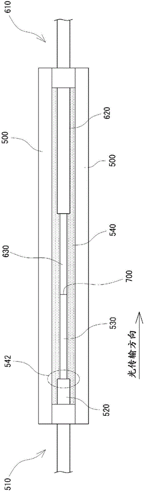
[0050] First, as a comparative example, a figure 1 Shown is the existing residual light removal configuration. As the double-clad optical fiber 510, 610, a double-clad optical fiber having a diameter of 10 μm in the core and a diameter of 400 μm in the cladding 530, 630 was used. The ends of the respective cladding members 520, 620 of the double-clad optical fibers 510, 610 were removed in the axial direction by 20 mm at a time, thereby exposing the claddings 530, 630. Ultrasonic cleaning using ethanol was performed to clean the exposed surfaces of the cladding layers 530 and 630 .

[0051]The claddings 530 , 630 of the above-mentioned double-clad optical fibers 510 , 610 are butt-fused in the reinforcement member 500 made of a ceramic member whose linear expansion coefficient matches that of silica glass. The remaining excitation light propagating in the claddings 530 and 630 is calculated based on the length of the double-clad fiber (clad pumping fiber) 510 and the claddin...

Embodiment 2

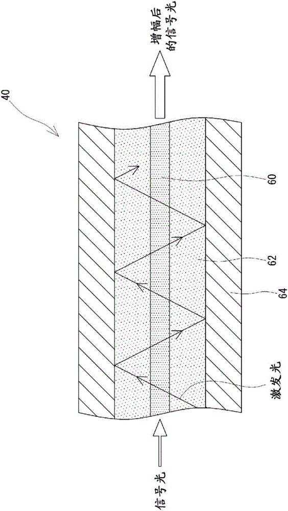
[0058] As Example 2, a Figure 4 The residual light removal configuration 70 is shown. As the cladding pumping fiber 40 , a cladding pumping fiber having a diameter of the core 60 of 10 μm and a diameter of the cladding 62 of 400 μm was used. use Figure 8 The apparatus 80 shown cuts the cladding 64 near the exit end of the clad pump fiber 40 . That is, the blade 84 was brought into contact with the surface of the clad pump fiber 40 and moved 30 mm in the longitudinal direction of the clad pump fiber 40 to expose the clad 62 from the clad 64 . Then, the angle of the clad pump fiber 40 was rotated around the axis by 20°, and cutting was performed a total of three times, so that it was exposed at an angle of 60° in total.

[0059] A ceramic member having a linear expansion coefficient equal to that of silica glass is used as the optical fiber housing portion 72 , and a hard UV curable resin is used as the resin 77 arranged at both ends of the optical fiber housing portion 72 ...


PUM


Abstract

This structure for eliminating excess light (70) is employed for eliminating excess light in a double-clad fiber (40) having a core (60), a cladding (62) of lower refractive index than the core (60), and a covering material (64) of lower refractive index than the cladding (62). The structure for eliminating excess light (70) is provided with: a fiber housing part (72) for housing a portion of the double-clad fiber (40); an exposed cladding part (74) in which a portion of the total circumference of the cladding (62) is exposed from the covering material (64) within the fiber housing part (72), along the lengthwise direction of the double-clad fiber (40); and a resin (76) filling the fiber housing part (72) interior and covering at least the exposed cladding part (74). The resin (76) has a refractive index equal to or greater than the refractive index of the cladding (62). The exposed cladding part (74), viewed in cross section perpendicular to the axis of the double-clad fiber (40), is formed, e.g., at angle of less than 180-degree centered on the axis.

Description

technical field [0001] The present invention relates to a residual light removal structure, and more particularly to a residual light removal structure for removing residual light from light propagating through an optical fiber of a fiber laser. Background technique [0002] In a cladding-excited fiber laser using a double-clad fiber, excitation light not absorbed by the core (residual excitation light) propagates through the cladding at the exit of the resonator. In particular, in a high-output fiber laser, since excitation light of a certain power is supplied, excess excitation light tends to be generated at the output portion of the resonator. Such residual excitation light propagates in a multi-mode manner, resulting in poor beam quality. Therefore, when such excess excitation light is emitted from the fiber laser together with the signal light, the quality of the output beam of the fiber laser deteriorates, making it impossible to achieve microfabrication using the out...

Claims


Application Information

Patent Timeline
Patent Type & Authority Applications(China)
IPC IPC(8): G02B6/02G02B6/036G02B6/44H01S3/067
CPCG02B6/14G02B6/4296H01S3/06729H01S3/06754H01S3/094007G02B6/264H01S3/0405
Inventor 田中弘范
Owner THE FUJIKURA CABLE WORKS LTD
Why Eureka
Try Eureka