Tunable mid-ir fiber laser for non-linear imaging applications

A fiber laser and fiber amplifier technology, applied in the field of nonlinear imaging, can solve the problem of low signal strength

Inactive Publication Date: 2016-09-28
THORLABS INC
View PDF6 Cites 1 Cited by
  • Summary
  • Abstract
  • Description
  • Claims
  • Application Information

AI Technical Summary

Problems solved by technology

However, spontaneous Raman scattering is a low-proba

Method used


Image

  • Tunable mid-ir fiber laser for non-linear imaging applications
  • Tunable mid-ir fiber laser for non-linear imaging applications
  • Tunable mid-ir fiber laser for non-linear imaging applications

Examples


Embodiment Construction

[0027] The description of illustrative embodiments in accordance with the principles of the invention is intended to be read in conjunction with the accompanying drawings, all of which are considered a part of the entire written description. In the description of the embodiments of the present invention disclosed herein, any reference to directions or orientations is only for convenience of description, and is not intended to limit the scope of the present invention in any way. Relative terms such as "below", "upper", "horizontal", "vertical", "above", "below", "upward", "downward" and their derivatives (for example, "horizontally" , "downwardly", "upwardly", etc.) should be construed to mean an orientation as described next or as shown in the figure in question. These relative terms are for convenience of description only and do not require that the device be constructed or operated in a particular orientation unless otherwise indicated. Terms such as "attached," "attached,"...


PUM

PropertyMeasurementUnit
Center wavelengthaaaaaaaaaa

Abstract

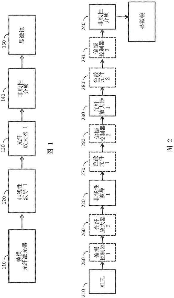
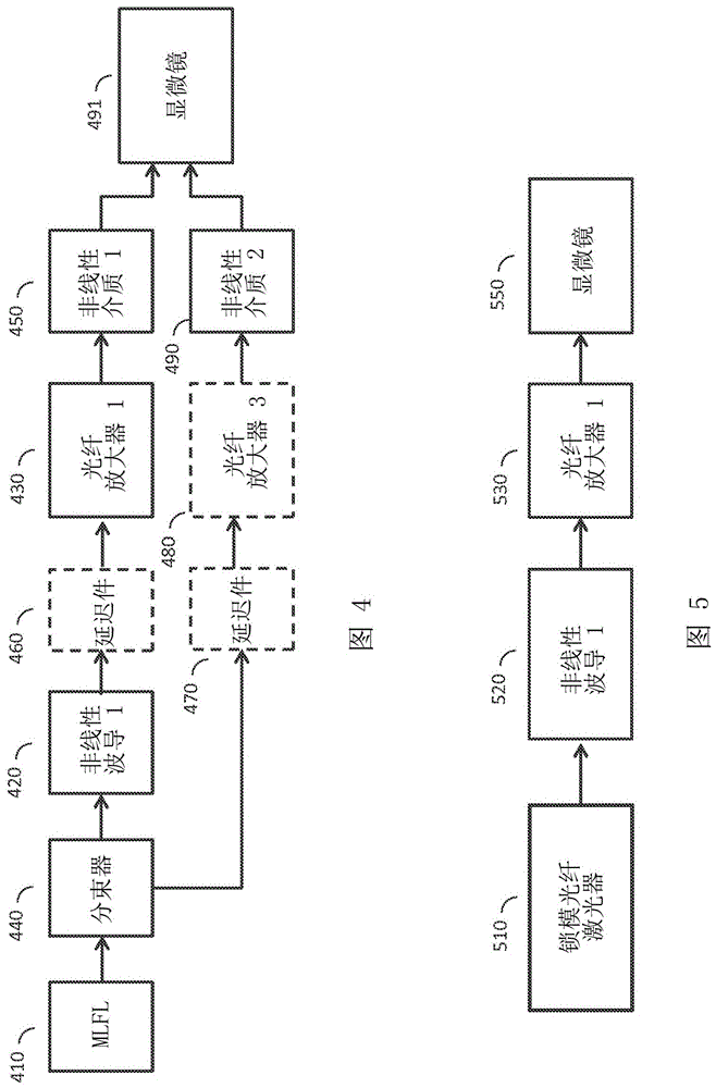
A microscopy system, including: a mode-locked fiber laser (110) configured to output a pulse having a center wavelength; a nonlinear waveguide (120) configured to shift the wavelength of the pulse from the mode-locked fiber laser; a fiber amplifier (130) configured to amplify the output from the first nonlinear waveguide; a second-harmonic generator (140) configured to generate femtosecond pulses at twice the optical frequency from the output of the fiber amplifier; and an imaging system (150).

Description

[0001] Cross References to Related Applications [0002] This application claims priority to US Provisional Application 61 / 924,629, filed January 7, 2014, the contents of which are incorporated herein by reference. technical field [0003] The present invention relates to nonlinear imaging, in particular to the field of microscopy applications. Background technique [0004] Nonlinear imaging, especially two-photon imaging systems, is the workhouse in today's medical and life science laboratories. [0005] A nonlinear imaging system consists of one or more excitation and detection beam paths and a processing unit. The excitation beam path consists of the laser, the optics to form the beam (i.e. beam expander), the 2D scanning unit, and a set of optics for relaying the beam onto the back aperture of the objective lens. Microscope objectives focus the beam of light onto the sample. The scanning unit is used to create a two-dimensional scanning pattern on the sample to illumi...

Claims


Application Information

Patent Timeline
IPC IPC(8): H01S3/067G01Q60/18
CPCG02B21/0032G02B21/0076G02B2207/114G02B21/361H01S3/1106H01S3/06754H01S3/0092G01N21/255G01N21/35G01N21/45G01N21/47G01N21/59G01N2021/3595H01S3/302
Inventor R·萨利姆P·芬德尔A·凯布尔
Owner THORLABS INC
Why Eureka
Try Eureka