Combined deep scarification and land preparation machine

A soil preparation machine and subsoiling technology, which is applied in the direction of agricultural machinery and equipment, agricultural machinery and implements, shovels, etc., can solve the problems of large traction resistance of deep plowing machinery, damage to the structure of the soil plow layer, and increase the economic burden of farmers. Consistency of plowing depth, smooth field surface, and the effect of ensuring the quality of land preparation operations

Inactive Publication Date: 2016-10-05
SHIHEZI UNIVERSITY
View PDF9 Cites 14 Cited by
  • Summary
  • Abstract
  • Description
  • Claims
  • Application Information

AI Technical Summary

Problems solved by technology

[0003] The problems existing in the existing soil preparation machinery are: the operation depth of the traditional rotary tillage machinery is small, and the long-term shallow tillage makes the soil form a thick and hard plow layer; the traction resistance of the deep tillage machinery is too large, and a high-horsepower tractor is required Traction, excessive energy consumption, increases the economic burden of farmers, on the other hand, deep plowing machinery will plow the deep soil to the surface, destroying the original soil plow layer structure, which is not conducive to crop growth
According to the nature of the operation, mechanized subsoiling can be divided into two modes: omnidirectional subsoiling and partial subsoiling. However, all-round subsoiling has a large amount of disturbance to the soil, and there is a large amount of water evaporation. During the subsoiling process, such as working resistance Large, too much energy consumption; local subsoiling has little disturbance to the soil, but subsoiling operation is difficult to ensure that the soil after subsoiling meets the requirements of flat field surface, finely broken soil, and consistent plowing depth

Method used


Image

  • Combined deep scarification and land preparation machine
  • Combined deep scarification and land preparation machine
  • Combined deep scarification and land preparation machine

Examples


Embodiment Construction

[0019] Below in conjunction with embodiment and accompanying drawing, the present invention will be described in further detail:

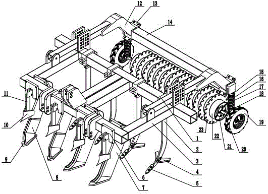
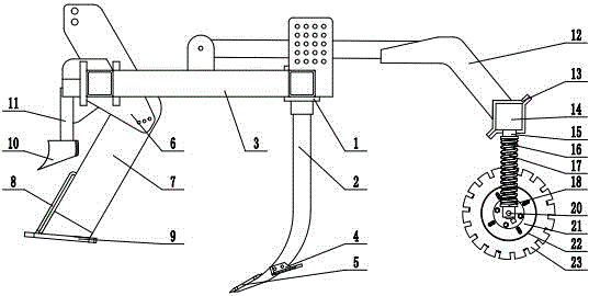
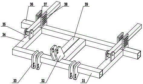
[0020] Refer to attached Figure 1~4 , the present invention is characterized in that it includes a frame 3, an omnidirectional subsoiling device and a plowing device. Before, described frame 3 is made of front beam 31, upper suspension plate 32, lower suspension plate 33, beam 34, fixed beam 39, fixed plate 35, limit plate 37, rear beam 36, support beam 38, and described The lower end surface of the upper suspension plate 32 is connected with the upper end surface of the front beam 31 and the upper end surface of the fixed cross beam 39, the lower suspension plate 33 embraces the front beam 31 and is connected, the front end surface of the cross beam 34 is connected to the inside of the front beam 31, and the lower end surface of the fixed plate 35 is connected to the Crossbeam 34 upper end face, support beam 38 front ends are connected with fixe...


PUM


Abstract

The invention relates to a combined deep scarification and land preparation machine which is characterized by comprising a rack, a full-direction deep scarification device and a turnover device, wherein the turnover device is arranged in front of the full-direction deep scarification device; the rack consists of a front beam, an upper suspended plate, lower suspended plates, transverse beams, fixed transverse beams, fixing plates, limiting plates, a rear beam and support beams; a partial deep scarification device is arranged on the rear beam; a soil crushing depth limiting device is arranged behind the support beams. According to the combined deep scarification and land preparation machine, a shallow layer and a conventional tillage mellow soil layer are loosened by using the turnover device, subsequently deep soil is cut by using the full-direction deep scarification device and is crushed by using the partial deep scarification device, furthermore the ploughed soil is crushed and flattened by using disc cutters in the soil crushing depth limiting device. In a word, by adopting the combined deep scarification and land preparation machine, combined soil preparation, shallow layer turnover operation, single full-direction deep scarification operation and partial deep scarification operation can be achieved according to agricultural requirements of different crops, the effect of one-machine multi-functions is achieved, the resistance can be reduced, the energy can be saved, and a good operation effect can be achieved.

Description

technical field [0001] The invention relates to a combined subsoiling machine. Background technique [0002] The cultivated land has been prepared by plowing or rotary tillage for a long time, resulting in thinning of the cultivated layer, compaction of the soil, increasing soil specific resistance year by year, and the need for more and more farming power. The widespread use of large-scale agricultural machinery such as high-horsepower tractors further intensifies the compaction of the soil, leading to a vicious circle, which makes the cultivated land form a thick and hard plow bottom layer. The existence of the plow stratum reduces the capacity of the plow layer and deteriorates the soil structure; it leads to more serious surface runoff and soil erosion, weakens the water storage capacity, and depletes farmland fertility; reduces soil porosity, limits the growth and development of plant roots, and reduces the stress resistance of crops , which restricts high and stable p...

Claims


Application Information

Patent Timeline
Patent Type & Authority Applications(China)
IPC IPC(8): A01B49/02
CPCA01B49/02Y02P60/14
Inventor 李霞汤明军王维新屈通张思远闫毅敏
Owner SHIHEZI UNIVERSITY
Why Eureka
Try Eureka