
a vacuum circuit

A loop and vacuum technology, applied in the direction of manipulators, chucks, manufacturing tools, etc., can solve the problems of high consumption of compressed air, unmaintainable vacuum state, workpiece falling, etc., to achieve the effect of sharply reducing consumption and shortening the duration.

Active Publication Date: 2018-08-14
STAR SEIKI XIANGYANG
View PDF8 Cites 0 Cited by
  • Summary
  • Abstract
  • Description
  • Claims
  • Application Information

AI Technical Summary

Problems solved by technology

[0003] 1. A large amount of compressed air needs to be continuously consumed when generating vacuum, and noise is continuously generated during the exhaust process;
[0004] 2. Because of static electricity, viscosity and other reasons, the micro products are adsorbed on the suction cup and cannot be removed;
[0005] 3. After a sudden power failure, it is impossible to judge whether the vacuum needs to be maintained or closed
However, the vacuum circuit cannot maintain a closed state after the single solenoid valve is powered off, and the vacuum is quickly destroyed.
This requires a single electric control supply solenoid valve to be continuously powered to maintain the vacuum state, which consumes a lot of compressed gas and electric energy while continuously generating vacuum.
Moreover, in the case of a sudden power failure, the vacuum state cannot be maintained, causing emergencies such as the workpiece falling, breaking or smashing the operator.

Method used


Image

  • a vacuum circuit

Examples


Embodiment Construction

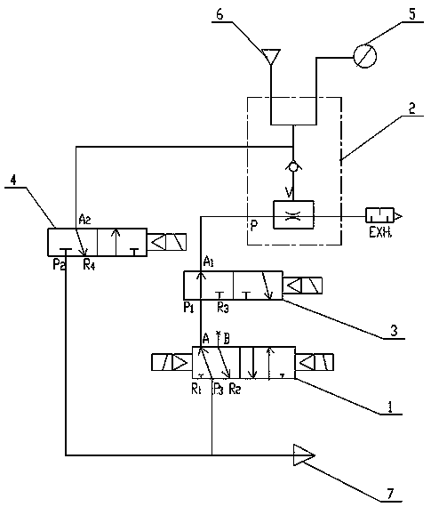
[0017] Such as figure 1 As shown, the double electric control supply solenoid valve 1 and the vacuum breaking valve 4 of the present invention are connected with the main air source 7, the main air source 7 is a compressed air source, and the double electric control supply solenoid valve 1 is connected to the vacuum generator through the energy-saving valve 3 2 is connected to the air inlet P port, the vacuum breaker valve 4 is connected to the air outlet V port of the vacuum generator 2, and a check valve is provided between the air outlet V port of the vacuum generator 2, the suction cup 6 and the negative pressure switch 5 to prevent Air flows back into the vacuum chamber from the silencer exhaust port EXH or the intake P port of the vacuum generator 2 .

[0018] The negative pressure switch 5 includes a negative pressure switch sensor and a negative pressure switch signal line; the negative pressure switch sensor is connected to the outlet V port of the vacuum generator 2,...


PUM


Abstract

The invention relates to a vacuum loop for automation equipment such as manipulators. A double-electronic control supply solenoid valve and a vacuum breaker valve are connected with a main gas source, the double-electronic control supply solenoid valve is connected with a gas inlet port of a vacuum generator by an energy saving valve, the vacuum breaker valve is connected with a gas outlet port of the vacuum generator, a one-way valve is arranged among the V port of the vacuum generator, a sucker and a negative pressure switch; a negative pressure switch sensor is connected with the gas outlet port of the vacuum generator, a negative pressure switch signal line is connected with the input port of a controller; the coils of the double-electronic control supply solenoid valve, the energy saving valve and the vacuum breaker valve are connected with the output port of the controller; two vacuum values are set in the controller, and the vacuum sorption confirmation signal value is set to be higher than the energy saving signal feedback value. The sealing state of the vacuum loop can be maintained, so that the consumption of the compressed air is sharply reduced, the duration time of noise is shortened, the problem that tiny products cannot be separated from the sucker is solved, and the vacuum state memory function under the condition of sudden power loss can be achieved.

Description

technical field [0001] The invention relates to the technical field of vacuum adsorption, in particular to a vacuum circuit for manipulators and automation equipment that integrates energy saving, vacuum breaking, and power-off vacuum memory. Background technique [0002] At present, most pick-up manipulators and automation devices use vacuum generators to absorb and transport objects, and use compressed air to convert positive pressure into negative pressure to generate vacuum, which can be used in conjunction with fixture plates to take out fine products. The vacuum generator has the advantages of small size, light weight and fast response, and is widely used. Its flaws are: [0003] 1. A large amount of compressed air needs to be continuously consumed when generating vacuum, and noise is continuously generated during the exhaust process; [0004] 2. Because of static electricity, viscosity and other reasons, the micro products are adsorbed on the suction cup and cannot ...

Claims


Application Information

Patent Timeline
Patent Type & Authority Patents(China)
IPC IPC(8): B25J15/06
Inventor 王俊王炼王明
Owner STAR SEIKI XIANGYANG
Learn More