Reflow soldering machine

A technology of reflow soldering and tin machine, which is applied in the direction of welding equipment, auxiliary devices, electrical components, etc., can solve the problems that the cooling effect of the fan is difficult to achieve, the quality of component welding is affected, and the quality of solder joints is greatly affected, so that it is easy to move and Fixed, guaranteed cooling effect, effect with obvious cooling effect

Inactive Publication Date: 2016-10-12
安徽广晟德自动化设备有限公司
View PDF6 Cites 1 Cited by
  • Summary
  • Abstract
  • Description
  • Claims
  • Application Information

AI Technical Summary

Problems solved by technology

Among them, the cooling speed after high-temperature soldering has a great influence on the quality of the solder joints. If the cooling is too slow, the brightness of the solder joints will not be high, and it will be easy to break and peel off; Solder joint crack
[0003] Existing reflow soldering machines generally only use a few heat dissipation fans to cool the PCB board, which can maintain the stability of the blowing efficiency, but the cooling speed of the PCB board is also affected by the ambient temperature, and the temperature in the workshop is too high or too low In the case of high temperature, the cooling speed is often greatly affected, which affects the quality of component welding, and it is difficult to achieve effective cooling by blindly increasing the fan speed under excessively high air temperature

Method used


Image

  • Reflow soldering machine
  • Reflow soldering machine
  • Reflow soldering machine

Examples


Embodiment Construction

[0030] The present invention will be further described in detail below in conjunction with the accompanying drawings and specific embodiments.

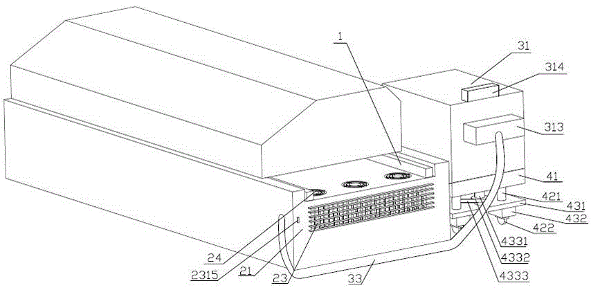
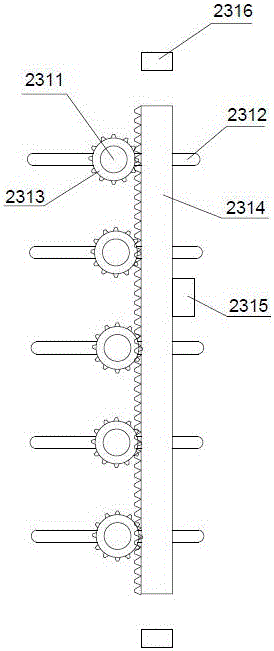
[0031] Such as Figure 1-5 As shown, the present invention includes a conveying track 1, an air cooling device arranged below the conveying track 1, and a water cooling mechanism connected to the air cooling device. Described air-cooling device comprises bellows 21, multiple fans, air inlet 23, air outlet 24, and described multiple fans are arranged at described air outlet 24 places, and described air inlet 23 is provided with flow adjustment device, and described flow adjustment The device includes a plurality of parallel turning shafts 2311, air regulating vanes 2312 arranged on the turning shafts 2311, a gear 2313 arranged at one end of the turning shafts 2311, a rack 2314 matching a plurality of said gears 2313, The rack 2314 is exposed to the toggle block 2315 outside the bellows, and the upper and lower sides of the rack 2314 a...


PUM


Abstract

A reflow soldering machine belongs to the technical field of the reflow soldering machine. The reflow soldering machine comprises a conveying rail, an air-cooling device which is arranged below the conveying rail and a water-cooling mechanism which is connected with the air-cooling device. The air-cooling device comprises an air bellow, a plurality of fans, an air inlet port and air outlet ports. The plurality of fans are arranged at the air outlet ports and a flow adjusting device is arranged at the air inlet port. The water-cooling mechanism comprises a water storage tank, a plurality of cooling pipes, a return pipe and a return pump. The water storage tank is arranged on one side of the reflow soldering machine and provided with a water inlet port and a water outlet port. A heat dissipating device is arranged at the water inlet port. The plurality of cooling pipes are arranged in the air bellow. One end of each cooling pipe is connected with the water outlet port and the other end of each cooling pipe is connected with the return pipe. The return pipe is connected with the cooling pipes and the water inlet port. The heat dissipating device comprises a heat dissipating groove, a rotary shaft which is arranged at the groove opening of the heat dissipating groove and a plurality of heat dissipating sheets which are arranged at the rotary shaft. Heat dissipating strips are arranged on both two side surfaces of each heat dissipating sheet. The water storage tank is further provided with an ice-cooling device. The machine is capable of adapting to the environment temperature and ensuring a suitable cooling speed after PCB welding, so that the welding quality can be guaranteed.

Description

technical field [0001] The invention relates to the technical field of reflow soldering machines, in particular to a reflow soldering machine. Background technique [0002] The reflow soldering machine is a commonly used soldering equipment in the surface mount industry. Its processing mainly includes: 1. Place one or more PCB circuit boards in the heating box of the reflow soldering machine; 2. Pass through evenly distributed heating tubes Evenly heat the PCB circuit board in a high temperature environment, and after a certain period of time, complete the one-time soldering of the solder joints on the surface of the PCB circuit board; 3. Turn on the cooling fan on the heating box to quickly cool the PCB circuit board, take out the PCB circuit board, The welding process is complete. Among them, the cooling speed after high-temperature soldering has a great influence on the quality of the solder joints. If the cooling is too slow, the brightness of the solder joints will not...

Claims


Application Information

Patent Timeline
Patent Type & Authority Applications(China)
IPC IPC(8): B23K3/08H05K3/34B23K101/42
CPCB23K3/085B23K2101/42H05K3/341
Inventor 符永胜张先文丁亚平
Owner 安徽广晟德自动化设备有限公司
Why Eureka
Try Eureka