Method for welding door frame of ultra-low-temperature high-power wind turbine tower

A technology of wind power tower and welding method, applied in welding equipment, auxiliary welding equipment, welding/cutting auxiliary equipment, etc., can solve the problem of difficult welding, difficult quality assurance, unqualified tower flange flatness and ovality, etc. It is beneficial to achieve anti-fatigue performance and anti-stress corrosion performance, eliminate residual tensile stress on the surface, and improve the first pass rate.

Active Publication Date: 2016-10-12
SINOHYDRO BUREAU 4 JIUQUAN NEW ENERGY EQUIPCO
View PDF5 Cites 13 Cited by
  • Summary
  • Abstract
  • Description
  • Claims
  • Application Information

AI Technical Summary

Problems solved by technology

In the manufacture of wind power towers, due to the opening at the door frame, the overall circumferential stress distribution of the tower is destroyed, and it is easy to affect the plane of the nozzle; the flange and the tower form a combined fillet weld, resulting in the door frame becoming a whole section of the tower. The stress concentration of the cylinder, and the welding seam filling is large, the number of welding seam layers is large, the welding seam cooling speed is fast, the probability of welding cracks is greatly increased, the welding is difficult, and defects such as cold cracks and lamellar tearing are easy to occur
In addition, the welding deformation of the door frame welds has a great influence on the flatness and ellipticity of the wind power tower flange, which may easily cause the flatness and ellipticity of the tower flange to fail
The material of the tower is Q345E, which must guarantee the low-temperature impact energy of -40°C. The requirements for the weld between the door frame and the tower are high, and the welding is difficult. Generally, manual arc welding is used for welding, which has production problems such as low production efficiency and difficult quality assurance.

Method used


Image

  • Method for welding door frame of ultra-low-temperature high-power wind turbine tower
  • Method for welding door frame of ultra-low-temperature high-power wind turbine tower
  • Method for welding door frame of ultra-low-temperature high-power wind turbine tower

Examples


Embodiment Construction

[0031] The present invention is described in detail below in conjunction with accompanying drawing:

[0032] The invention discloses a method for welding a door frame of an ultra-low temperature and high-power wind power tower, comprising the following steps:

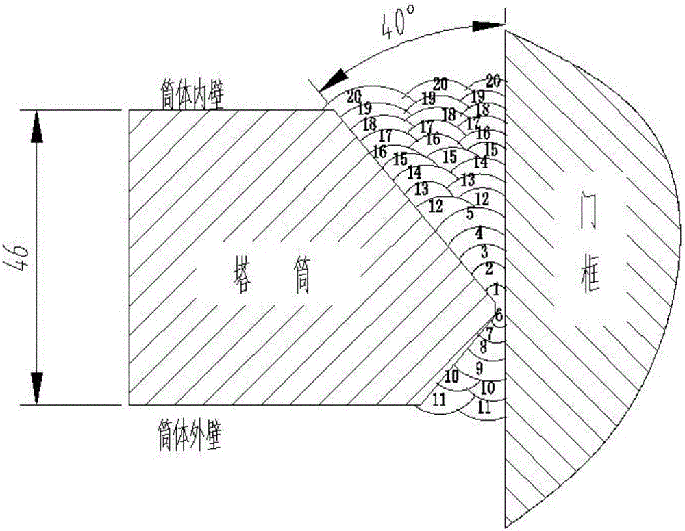
[0033] (1) Door frame material preparation: The door frame material preparation is prepared by splicing two parts. The unloaded steel plate is rolled into shape by a plate rolling machine. Stress concentration is not avoided. The splicing seams are located on both sides of the door frame center line. 150mm, control the flame heating range, reduce the influence of the metallographic structure of the cutting plate, assemble and weld the two formed door frames; or use thick plates to cut and blank the whole by CNC programming;

[0034] (2) Door opening cutting: Before cutting the door opening, adjust the installation axis of the tower tube to the basic horizontal state, use the door frame as a physical template, draw a lin...


PUM


Abstract

The invention discloses a method for welding a door frame of an ultra-low-temperature high-power wind turbine tower. The method comprises the following five main steps: preparing materials of the door frame; cutting a door hole; mounting an anti-deformation tool; welding corner weld of the door frame and the tower; and carrying out stress relief treatment after welding. Stress concentration of a welding region of the door frame and the tower under the working condition of ultra-low temperature and the condition of high-power generation requirements can be eliminated, defects of welding cracks and lamellar tearing are avoided, and requirements of impact energy at the low temperature of minus 40 DEG C are met; influences of stress concentration to yield of flatness and ovality of a flange of the tower is avoided; and first-pass yield of inspection and acceptance of the tower is improved.

Description

technical field [0001] The invention relates to a welding operation process for a door frame of a wind power tower, in particular to an ultra-low temperature and high-power wind power tower door frame welding method. Background technique [0002] The wind turbine tower is the key equipment to support the normal operation of the wind turbine and blades. The access door of the tower tube is the only channel for the installation and operation staff to enter the unit. The access door frame has the functions of fixing the access door panel and reinforcing the opening area of ​​the tower tube. It is generally made of 60-200mm steel plate processing. In the manufacture of wind power towers, due to the opening at the door frame, the overall circumferential stress distribution of the tower is destroyed, and it is easy to affect the plane of the nozzle; the flange and the tower form a combined fillet weld, causing the door frame to become a whole section of the tower. The stress conc...

Claims


Application Information

Patent Timeline
Patent Type & Authority Applications(China)
IPC IPC(8): B23K37/00
CPCB23K37/00
Inventor 朱锴年裘学强董贵林张阳勇管伟魏霏霏缪飞燕王引朱倩
Owner SINOHYDRO BUREAU 4 JIUQUAN NEW ENERGY EQUIPCO
Why Eureka
Try Eureka