Working method for joint robot for assembly

A working method and robot technology, applied in manipulators, metal processing, manufacturing tools, etc., can solve the problems of poor work stability, high operating costs, horizontal and vertical offsets, etc., and achieve high workpiece calibration accuracy and low operating costs. , the effect of simple working process

Inactive Publication Date: 2016-10-12
苏州塞默机械有限公司
View PDF6 Cites 9 Cited by
  • Summary
  • Abstract
  • Description
  • Claims
  • Application Information

AI Technical Summary

Problems solved by technology

[0004] 1. Each mechanical axis is prone to horizontal and vertical deviations during the working process, and it is impossible to accurately calibrate the station;
[0005] 2. The overall working process of the robot is relatively complicated, with high load requirements, slow assembly speed, and high operating costs;
[0006] 3. When the spline shaft goes down, it will generate a large axial impact force, so it is very easy to damage the workpiece during work, and the work stability is poor

Method used


Image

  • Working method for joint robot for assembly

Examples


Embodiment 1

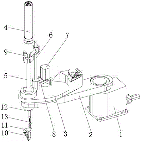
[0024] Such as figure 1 As shown, the working method of a joint robot for assembly in this embodiment, the specific working steps are as follows:

[0025] (1) First, turn on the power switch, and after the staff set the working parameters, the first joint axis 2 and the second joint axis 3 on the machine base 1 start to rotate and adjust in the horizontal direction under the drive of the servo motor;

[0026] (2) Screws or rivets enter the claw head 10 through the vacuum nozzle 11 under the action of the suction head assembly 13;

[0027] (3), the synchronous belt 8 drives the screw rod 6 and the buffer mechanism 9 sequentially under the drive of the motor 7, and drives the spline shaft 5 connected with the screwdriver head at the bottom end to pass through the connecting sleeve 12 and push toward the screw;

[0028] (4) After the screwdriver head calibrates the screw, the spline shaft 5 is driven by the motor 4 to drive the screwdriver head to rotate and press down until the...

Embodiment 2

[0032] Such as figure 1 As shown, the working method of a joint robot for assembly in this embodiment, the specific working steps are as follows:

[0033] (1) First, turn on the power switch, and after the staff set the working parameters, the first joint axis 2 and the second joint axis 3 on the machine base 1 start to rotate and adjust in the horizontal direction under the drive of the servo motor;

[0034] (2) The rivet enters the claw head 10 through the vacuum nozzle 11 under the action of the suction head assembly 13;

[0035] (3), the synchronous belt 8 drives the screw rod 6 and the buffer mechanism 9 in turn under the drive of the motor 7, and drives the spline shaft 5 connected with the riveted joint at the bottom end to pass through the connecting sleeve 12 and push toward the rivet;

[0036] (4) After the rivet joint calibrates the rivet, the spline shaft 5 is driven by the motor 4 to drive the rivet joint to rotate and press down until the assembly is completed; ...


PUM


Abstract

The invention discloses a working method for a joint robot for assembly, and mainly relates to the technical field of the joint robot. The working method comprises the following steps: a first joint shaft and a second joint shaft on a machine base are driven by a servo motor to start rotary regulation in the horizontal direction; under action of a sucker assembly, a bolt or a rivet enters a gripper head through a vacuum suction nozzle; a synchronous belt is driven by a motor to sequentially drive a lead screw and a buffer mechanism, and to drive a spline shaft with a screwdriver head or a riveting head at the bottom end to pass through a connecting sleeve for jacking the bolt or rivet; after the bolt or the rivet is calibrated by the screwdriver head or the riveting head, the spline shaft is driven by an electric motor to drive the screwdriver head or the riveting head to rotate and press together until assembly is completed; and finally, the spline shaft is driven by the motor to drive the screwdriver head or the riveting head to move upwards to wait for a next-time working order. The working method is precise in station calibration, is high in assembly speed, is low in load requirement, is not liable to damage a workpiece during working, and is low in operation cost.

Description

technical field [0001] The invention relates to the technical field of joint robots, in particular to a working method of joint robots for assembly. Background technique [0002] Joint robot, also known as joint arm robot or joint robot arm, is one of the most common forms of industrial robots in today's industrial field. It is suitable for mechanical automation operations in many industrial fields, such as automatic assembly, painting, handling, welding, etc. Work. Among them, the assembly joint robot generates rotational power through electric or pneumatic means to replace frequent manual assembly actions, which reduces the work intensity of assembly to some extent. [0003] In recent years, with the continuous development of science and technology, various industries have higher and higher technical requirements for assembly joint robots. However, the existing working methods of assembly joint robots still have the following defects: [0004] 1. Each mechanical axis is ...

Claims


Application Information

Patent Timeline
Patent Type & Authority Applications(China)
IPC IPC(8): B25J11/00B23P19/06B21J15/10
CPCB25J11/005B21J15/10B23P19/06B25J11/007
Inventor 黎燕俠
Owner 苏州塞默机械有限公司
Why Eureka
Try Eureka