New energy automobile ultralow-temperature heat pump air conditioner system and control method

A new energy vehicle and air-conditioning system technology, which is applied in the ultra-low temperature heat pump air-conditioning system and control field of new energy vehicles. It can solve problems such as increasing the burden on the compressor, affecting driving safety, and increasing the power consumption of the compressor. It achieves a simple and stable loop structure. The effect of expanding the scope of use and flexible opening methods

Active Publication Date: 2016-10-12
SOUTH AIR INT
View PDF7 Cites 7 Cited by
  • Summary
  • Abstract
  • Description
  • Claims
  • Application Information

AI Technical Summary

Problems solved by technology

[0006] 1. When the heat exchanger outside the car is used as an evaporator, it is easy to frost, which will increase the power consumption of the compressor and even damage the system. When defrosting by simply relying on the system to stop the operation or switching to AC mode, not only cannot effectively solve the large area The problem of defrosting will also cause drastic temperature fluctuations in the passenger compartment, seriously affecting comfort
[0007] 2. The heating in the long-term internal circulation mode is prone to fogging of the windshield. The heat pump system designed with only one heat exchanger in the air-conditioning box cannot dehumidify the cabin, which will seriously affect driving safety.
[0008] 3. When working in a general low temperature environment (0℃~-10℃), the suction temperature of the compressor is low. In order to meet the heating requirements, it is necessary to maintain a high temperature exhaust gas, which increases the burden on the compressor and causes a low COP. Can not meet the needs of rapid heating;
[0009] 4. Generally, the working limit of (low temperature) heat pump system is around -10°C, which limits the use area of ​​electric vehicles equipped with this system

Method used


Image

  • New energy automobile ultralow-temperature heat pump air conditioner system and control method
  • New energy automobile ultralow-temperature heat pump air conditioner system and control method
  • New energy automobile ultralow-temperature heat pump air conditioner system and control method

Examples


Embodiment Construction

[0029] Hereinafter, the preferred embodiments of the present invention will be described in detail with reference to the accompanying drawings.

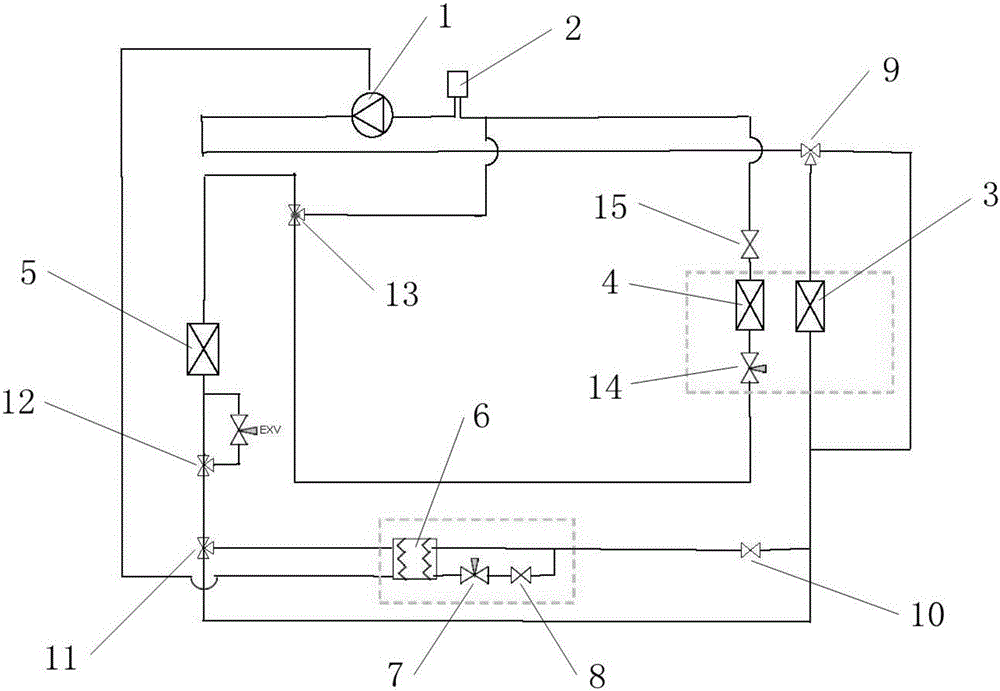
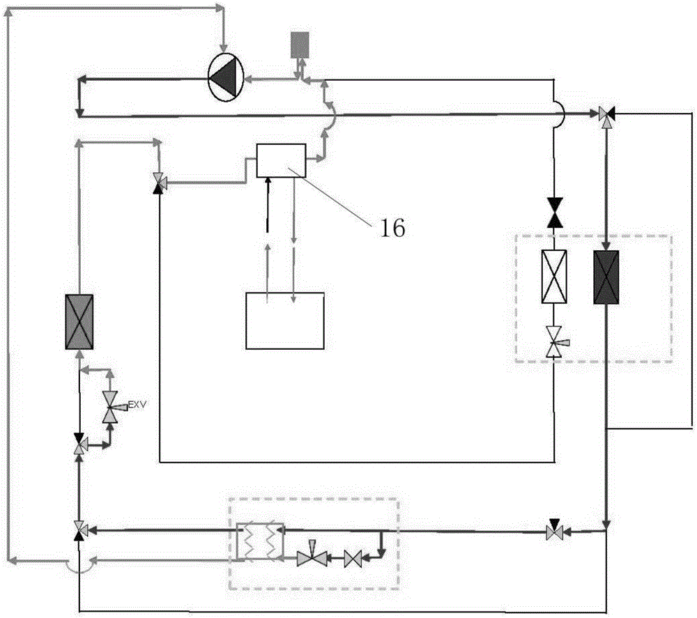
[0030] As shown in the figure, the ultra-low temperature heat pump air conditioning system for new energy vehicles of the present invention includes a compressor 1, a gas-liquid separator 2, an in-vehicle heat exchanger 3, an evaporator 4, an outside heat exchanger 5, and a steam ejector 6 One inlet end of the steam ejector 6 is connected in series with TXVI7 and the outlet end of the two-way valve II8, and the inlet end of the two-way valve II8 is connected in parallel with the other inlet end of the steam ejector 6; the compressor 1 The high-pressure port is connected to the interior heat exchanger 3 through the three-way reversing valve I9, and the interior heat exchanger 3 is connected to the inlet end of the two-way valve II8 through the two-way valve III10, and the steam ejector 6 One outlet end of the vehicle is connected to the ...


PUM


Abstract

The invention discloses a new energy automobile ultralow-temperature heat pump air conditioner system and a control method. The modes of refrigerating, heating, dehumidifying and defrosting can be achieved by adjusting the loop connecting modes, and the characteristic of simple and stable loop structure is achieved. In the heating mode, two refrigerant travelling paths are formed, the workload of an automobile external heat exchanger is reduced, enthalpy of a compressor is increased, the working efficiency of the compressor is effectively improved, and the reliability of the system is ensured; in the refrigerating mode and the defrosting mode, direct communicating bypasses are used for avoiding unnecessary parts, refrigerant pressure drop can be reduced, and flow resistance is reduced, so that load of the compressor is reduced, and the working efficiency of the compressor is improved; and the opening mode of the bypasses is flexible, control is easy, adaptability regulation can be conducted according to actual using conditions, and the using range is enlarged.

Description

Technical field [0001] The invention belongs to the field of automobile air conditioning, and specifically relates to a new energy automobile ultra-low temperature heat pump air conditioning system and a control method. Background technique [0002] There are currently two types of air-conditioning systems. The first is the traditional air-conditioning system used in fuel vehicles, and the second is the heat pump air-conditioning system used in electric vehicles. [0003] The traditional automobile air conditioning system consists of an evaporator, an expansion valve, a condenser, a number of pipelines and a compressor. The compressor is driven by the engine through a pulley. In the seasons with higher temperatures, the HVAC evaporator absorbs the heat in the passenger compartment to achieve the purpose of cooling; in the seasons with lower temperatures, the heating is achieved by heating the gas through the core of the engine's high-temperature coolant. [0004] For electric vehicl...

Claims


Application Information

Patent Timeline
IPC IPC(8): B60H1/00
CPCB60H1/00385B60H1/00899
Inventor 王晓勇黄龙李广苏涛
Owner SOUTH AIR INT
Why Eureka
Try Eureka