Low-stress dipping pipe for RH vacuum furnace

A low-stress, dipped tube technology, applied in the field of RH vacuum furnaces in steelmaking plants, can solve problems such as castable outer lining life synchronization, thermal stress damage, and dipped tube service life wandering, so as to reduce structural stress and low thermal stress, The effect of prolonging the service life and improving the ability to resist crack spalling and damage

Active Publication Date: 2016-10-12
武汉钢铁有限公司
View PDF8 Cites 1 Cited by
  • Summary
  • Abstract
  • Description
  • Claims
  • Application Information

AI Technical Summary

Problems solved by technology

[0004] To sum up, scholars at home and abroad have carried out a lot of research work on longevity technology from the aspects of RH vacuum furnace dip tube structure, preparation materials and preparation technology, and on-site maintenance. However, the damage form of dip tube has not changed, and the castable The service life of the lining is still not synchronized with that of the refractory brick lining, the bottom of the dipping tube is still the hardest hit area for the dipping tube to be damaged, and the service life of the dipping tube is still long-term. The problem of damage still requires continuous research and improvement by those skilled in the art

Method used


Image

  • Low-stress dipping pipe for RH vacuum furnace
  • Low-stress dipping pipe for RH vacuum furnace
  • Low-stress dipping pipe for RH vacuum furnace

Examples


Embodiment 1

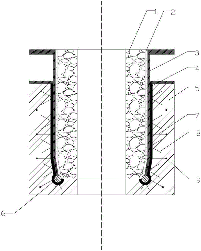
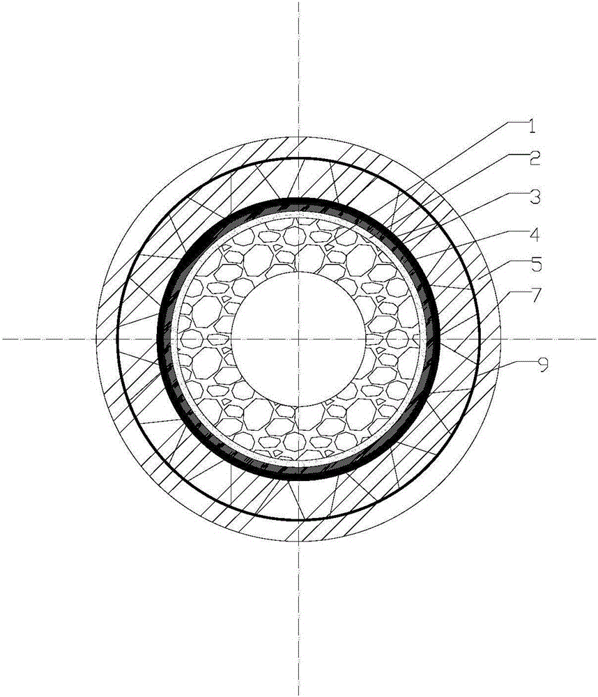
[0024] Such as figure 1 with 3 Shown: a RH vacuum furnace low-stress impregnated pipe, which includes a refractory brick lining 1, a filling layer 2 and a steel cylinder 3 from the inside to the outside; The dense layer is filled with ramming material fine powder, wherein, the raw materials of magnesia-chrome dry ramming material fine powder are composed of 80%-85% waste magnesia-chrome brick fine powder, 5%-10% Cr 2 o 3 Micropowder, 2% to 5% thermosetting phenolic resin powder, 1% to 3% boric acid and 1% to 3% sodium metasilicate; the particle size of waste magnesia chrome brick powder is less than 0.044mm.

[0025] The wall of the steel cylinder 3 has no holes, and the upper part of the steel cylinder 3 is a straight cylinder and the lower part is an inner cone cylinder. The bottom surface of the steel cylinder 3 is welded with an annular metal round rod 6, and the annular metal round tube 6 is densely filled with the same material as the outer lining of the castable. cas...

Embodiment 2

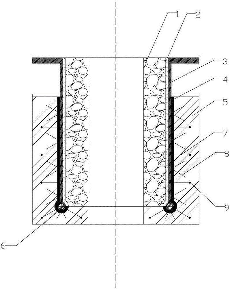
[0031] Such as figure 2 with 3 Shown: the RH vacuum furnace low-stress dipping tube of this embodiment is basically the same as that of Embodiment 1, the differences:

[0032] The steel cylinder 3 is an integral straight cylinder, and the bottom surface of the steel cylinder 3 is welded with an annular metal tube 6 .


PUM

PropertyMeasurementUnit
particle sizeaaaaaaaaaa
diameteraaaaaaaaaa

Abstract

The invention discloses a low-stress dipping pipe for an RH vacuum furnace. The low-stress dipping pipe sequentially comprises a refractory brick lining, a filling layer and a steel barrel from inside to outside. No hole is formed in the wall surface of the steel barrel. An annular round metal pipe or an annular round metal rod is welded to the bottom surface of the steel barrel. The outer wall of the lower portion of the top of the steel barrel and the outer wall of the annular round metal pipe or the outer wall of the annular round metal rod are each paved with a buffer layer. V-shaped metal anchoring pieces and double-V-shaped metal anchoring pieces are uniformly welded to the outer wall of the steel barrel or the outer wall of the annular round metal rod in the axial spaced layered circumferential direction of the steel barrel and penetrate through the buffer layers. According to the low-stress dipping pipe for the RH vacuum furnace, the problem that damage and deterioration are caused due to the fact that the difference of the material performances of all components in a dipping pipe complex structure is remarkable is effectively solved, and the comprehensive purposes of reducing the structural stress and the heat stress of the dipping pipe, improving the dipping pipe resistance to crack, stripping and damage and the integrality and the structural stability of the dipping pipe, prolonging the service life of the dipping pipe and the like are achieved.

Description

technical field [0001] The invention relates to a RH vacuum furnace in a steelmaking plant, in particular to a low-stress impregnated tube of the RH vacuum furnace. Background technique [0002] Molten steel vacuum treatment technology adopts RH vacuum furnace to refine molten steel outside the furnace to remove hydrogen and impurities in molten steel and produce high-purity steel. RH vacuum treatment technology is a multi-functional secondary refining method with advanced technology and can effectively improve the quality of molten steel. The RH vacuum furnace consists of 1 RH vacuum chamber and 2 RH vacuum furnace dip tubes (rising tube and downcomer) located at the bottom. During the external refining process of the RH vacuum furnace, the dipping tube is immersed in molten steel, the vacuum chamber is evacuated, and argon gas is blown from the rising tube of the dipping tube to make the molten steel in the ladle enter the vacuum chamber from the rising tube, and then fro...

Claims


Application Information

Patent Timeline
Patent Type & Authority Applications(China)
IPC IPC(8): C21C7/10
CPCC21C7/10
Inventor 欧阳德刚罗安智
Owner 武汉钢铁有限公司
Why Eureka
Try Eureka