Novel hydraulic oscillator with energy gathering and damping functions

A hydraulic oscillator, a new type of technology, applied in the field of new hydraulic oscillators and new downhole drilling tools, can solve the problems of large friction resistance, prone to downhole accidents, low drilling pressure transmission efficiency, etc., to achieve efficient rock breaking and alleviate stick-slip Phenomenon, the effect of reducing the number of trips

Active Publication Date: 2016-10-12
江苏弘业检测技术有限公司
View PDF5 Cites 10 Cited by
  • Summary
  • Abstract
  • Description
  • Claims
  • Application Information

AI Technical Summary

Problems solved by technology

[0004] In order to explore and solve the problems described in the background technology that the friction between the drill string and the well wall is relatively large, the transmission efficiency of the weight on bit is low, and downhole accidents are prone to occur during the drilling process, the present invention provides a The new type hydraulic oscillator of the present invention utilizes the multi-stage vibration absorbing ring to absorb the vibration generated by the upper tool when the oscillator is working, so as to ensure that the normal operation of the upper drilling tool is not affected, and the vibration is transmitted through the series disc spring and the spline. WOB and torque, when the drilling fluid flows through the diversion tube, the drilling fluid enters the pressure chamber through the inlet diversion hole on the circumference of the diversion tube, and then flows back to the central flow channel through the outlet diversion hole. Drilling fluid pressure pulsates and fluctuates, and the oscillation assembly produces oscillation, thereby improving drilling efficiency

Method used


Image

  • Novel hydraulic oscillator with energy gathering and damping functions
  • Novel hydraulic oscillator with energy gathering and damping functions
  • Novel hydraulic oscillator with energy gathering and damping functions

Examples


Embodiment Construction

[0014] The present invention will be further described below in conjunction with accompanying drawing:

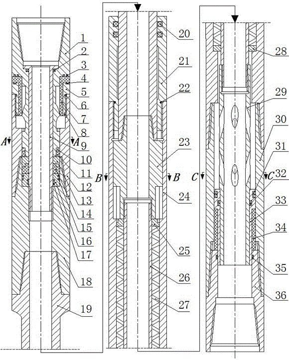
[0015] see figure 1 , The new type hydraulic oscillator with energy-gathering and shock-absorbing function is composed of three parts: a shock-absorbing assembly, a transmission assembly, and an oscillation assembly. The front end of the transmission assembly is equipped with an oscillation assembly, and the rear end is equipped with a shock-absorbing assembly. The shock absorbing assembly includes an upper body 1, a rectangular sealing ring a2, a rectangular sealing ring b3, a rectangular sealing ring c4, a locking joint 5, an O-shaped sealing ring a6, an upper vibration-absorbing ring 7, an upper locking ring 8, and a central Pipe 9, washer 10, middle vibration-absorbing ring 11, spline joint 12, lower locking ring 13, lower vibration-absorbing ring 14, rectangular sealing ring d15, sealing ring 16, rectangular sealing ring e17, intermediate nipple 18, and the rectangular...


PUM


Abstract

The invention relates to a novel hydraulic oscillator with energy gathering and damping functions. The novel hydraulic oscillator is fixedly mounted in the position close to a drill bit and comprises a damping assembly, a transmission assembly and an oscillating assembly. The oscillating assembly is mounted at the front end of the transmission assembly. The damping assembly is mounted at the rear end of the transmission assembly. Vibration generated on an upper tool by the oscillator during operating is absorbed through multiple stages of vibration absorption rings; bit pressure and torque are transmitted through a disk spring and splines, and the disk spring and the splines are connected in series. When flowing through a flow guide pipe, drilling fluid flows into a pressure chamber through flow guide holes in the circumference of the flow guide pipe and then flows back to a central flow channel, pressure pulsation of the drilling fluid fluctuates, and the oscillating assembly generates an oscillating effect. The novel hydraulic oscillator with the energy gathering and damping functions can generate the oscillating frequency of a certain range to reduce friction drag borne by a drilling tool in the rock breaking process of the drill bit, automatically absorb vibration and reduce the influence of the oscillating assembly on the upper drilling tool during operating, so that the well drilling efficiency is improved.

Description

technical field [0001] The invention belongs to the field of petroleum and natural gas drilling engineering and relates to a novel downhole drilling tool, in particular to a novel hydraulic oscillator with the function of energy gathering and shock absorption. Background technique [0002] At present, the demand for oil and gas at home and abroad is increasing, and many oil and gas reserves that are difficult to exploit are gradually entering the development stage to increase oil and gas production and meet people's growing energy needs. At the same time, with the continuous development of oil drilling technology, a large number of new downhole tools are constantly being developed and used, making the drilling of unconventional wells possible, especially the emergence of complex wells such as extended reach wells, multi-lateral horizontal wells, and highly deviated wells. Oil and gas that were previously unavailable for production are gradually being developed, and the numbe...

Claims


Application Information

Patent Timeline
Patent Type & Authority Applications(China)
IPC IPC(8): E21B28/00E21B17/07
CPCE21B17/07E21B28/00
Inventor 田家林杨应林杨琳胡书辉张堂佳杨毅林晓月
Owner 江苏弘业检测技术有限公司
Why Eureka
Try Eureka