Oil baffle plate, compressor rotor assembly, compressor and air conditioner

A compressor rotor and oil baffle technology, applied in the field of compressors, can solve the problems of high movement speed and large flow noise, and achieve the effects of reducing noise, reducing gas flow noise, and reducing oil content

Inactive Publication Date: 2016-10-12
ZHUHAI LANDA COMPRESSOR +1
View PDF5 Cites 6 Cited by
  • Summary
  • Abstract
  • Description
  • Claims
  • Application Information

AI Technical Summary

Problems solved by technology

When the airflow passes through, the movement speed is higher, and the flow noise is larger

Method used


Image

  • Oil baffle plate, compressor rotor assembly, compressor and air conditioner
  • Oil baffle plate, compressor rotor assembly, compressor and air conditioner
  • Oil baffle plate, compressor rotor assembly, compressor and air conditioner

Examples


Embodiment Construction

[0036] The core of the present invention is to provide an oil baffle to improve the oil-gas separation effect;

[0037] Another core of the present invention is to provide a compressor rotor assembly, a compressor and an air conditioner.

[0038] Hereinafter, an embodiment will be described with reference to the drawings. In addition, the examples shown below do not limit the content of the invention described in the claims in any way. In addition, all the contents of the configurations shown in the following embodiments are not limited to be essential to the solution of the invention described in the claims.

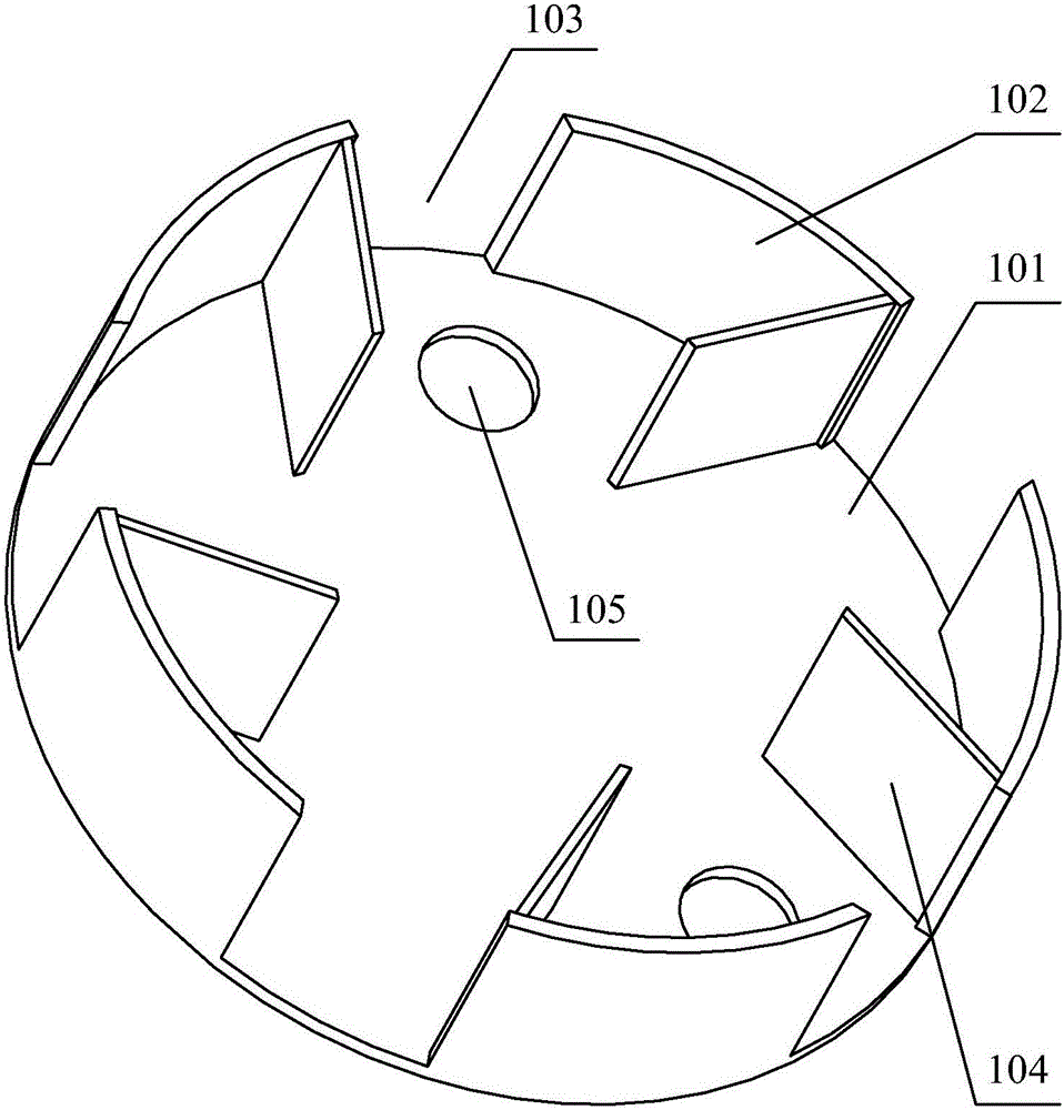
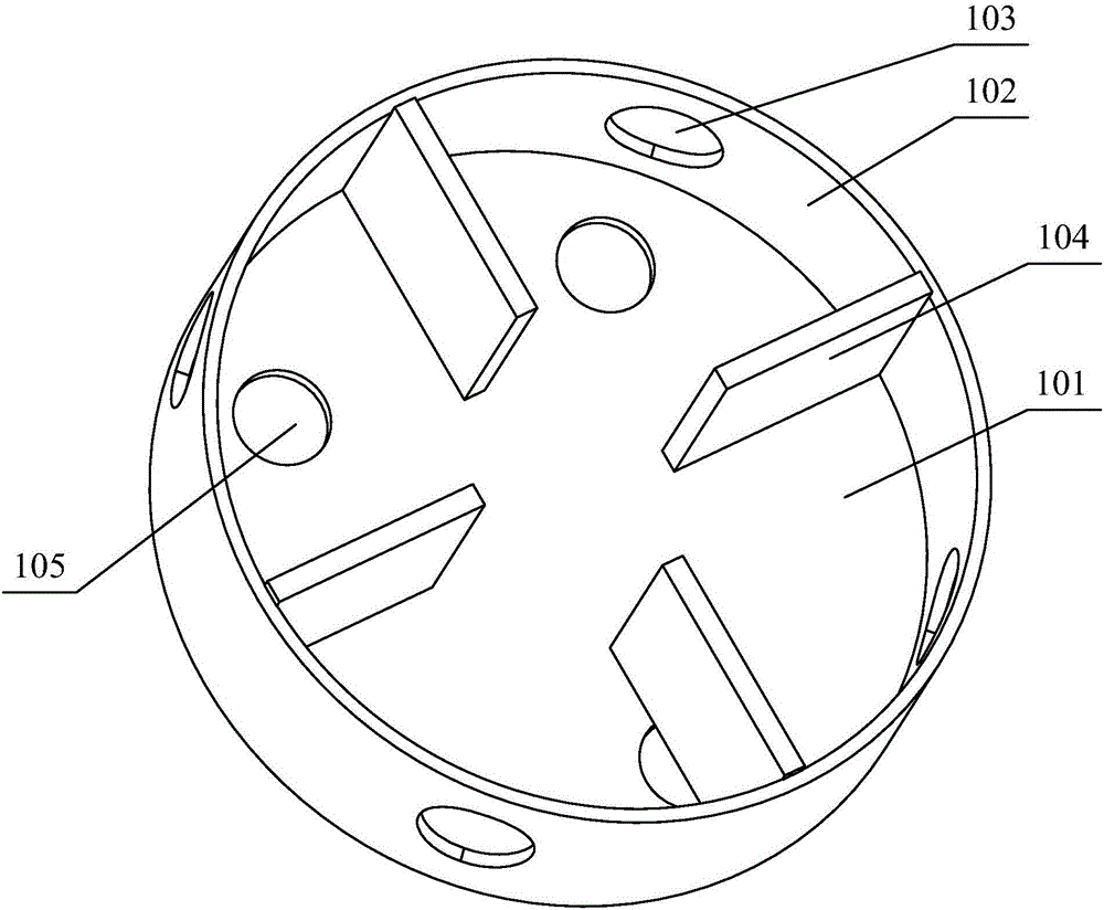
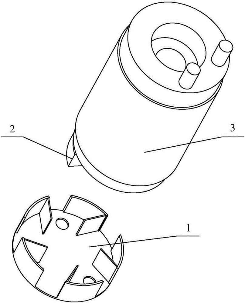
[0039] Such as figure 1 and image 3 As shown, the oil baffle provided by the embodiment of the present invention includes an oil baffle body. In order to facilitate the understanding of the arrangement position of the guide vanes 104, the present invention defines the side surface of the oil baffle body facing the rotor 3 as the oil-air separation surface. The focu...


PUM


Abstract

An oil baffle disclosed in an embodiment of the present invention includes an oil baffle body, the surface of the oil baffle body facing the rotor is an oil-gas separation surface, and an oil-gas separation surface arranged on the oil baffle body side guide vanes. For the oil baffle provided by the present invention, when the oil baffle rotates together with the rotor, the guide vanes located on the oil-air separation surface of the oil baffle body will rotate together with the oil baffle body, because the turbulence caused by the rotation of the guide vanes The function enhances the rotation strength of the refrigerant flow field and assists the gas circulation, thereby enhancing the separation effect of the oil-gas mixture, reducing the oil discharge of the compressor, and improving the overall performance of the compressor. The invention also discloses a compressor rotor assembly, a compressor and an air conditioner.

Description

technical field [0001] The invention relates to the technical field of compressors, in particular to an oil baffle, a compressor rotor assembly, a compressor and an air conditioner. Background technique [0002] The stator and rotor form the motor assembly of the compressor, and the compression pump body includes a cylinder, an upper flange, a lower flange and a roller fixed on the eccentric part of the crankshaft. When working, the rotor rotates inside the stator, and drives the rollers to roll eccentrically in the cylinder through the crankshaft. Under the action of the eccentric rolling of the rollers, the low-pressure refrigerant is sucked into the cylinder through the suction pipe and compressed until it reaches the pressure When the critical pressure is exceeded, it is output to the heat exchange system through the exhaust pipe. [0003] Refrigerated oil is stored at the bottom of the closed shell of the compressor. There is an oil channel through the crankshaft. Duri...

Claims


Application Information

Patent Timeline
Patent Type & Authority Applications(China)
IPC IPC(8): F04C29/02F04C29/06
CPCF04C29/026F04C29/068
Inventor 张继胤范少稳
Owner ZHUHAI LANDA COMPRESSOR
Why Eureka
Try Eureka