
An air source heat pump defrosting system with two-stage compression switched to partial binary cascade

An air source heat pump, two-stage compression technology, applied in lighting and heating equipment, damage protection, mechanical equipment, etc., can solve problems such as affecting indoor temperature, slow defrosting speed, and large system impact, and achieve improved heat exchange efficiency, The effect of reducing heat exchange temperature difference and low cost of renovation

Active Publication Date: 2018-07-17
江苏辛普森新能源有限公司
View PDF5 Cites 0 Cited by
  • Summary
  • Abstract
  • Description
  • Claims
  • Application Information

AI Technical Summary

Problems solved by technology

[0004] The purpose of the present invention is to provide an air source heat pump defrosting system in which two-stage compression is switched to partial binary cascade, so as to solve the problems of existing defrosting technologies such as large impact on the system, influence on indoor temperature, slow defrosting speed, and energy The problem of increased consumption

Method used


Image

  • An air source heat pump defrosting system with two-stage compression switched to partial binary cascade
  • An air source heat pump defrosting system with two-stage compression switched to partial binary cascade
  • An air source heat pump defrosting system with two-stage compression switched to partial binary cascade

Examples


Embodiment Construction

[0032] Specific embodiments of the present invention will be described in detail below in conjunction with the accompanying drawings.

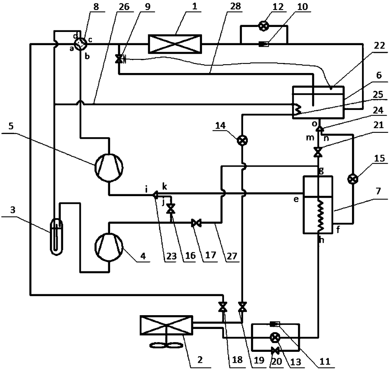
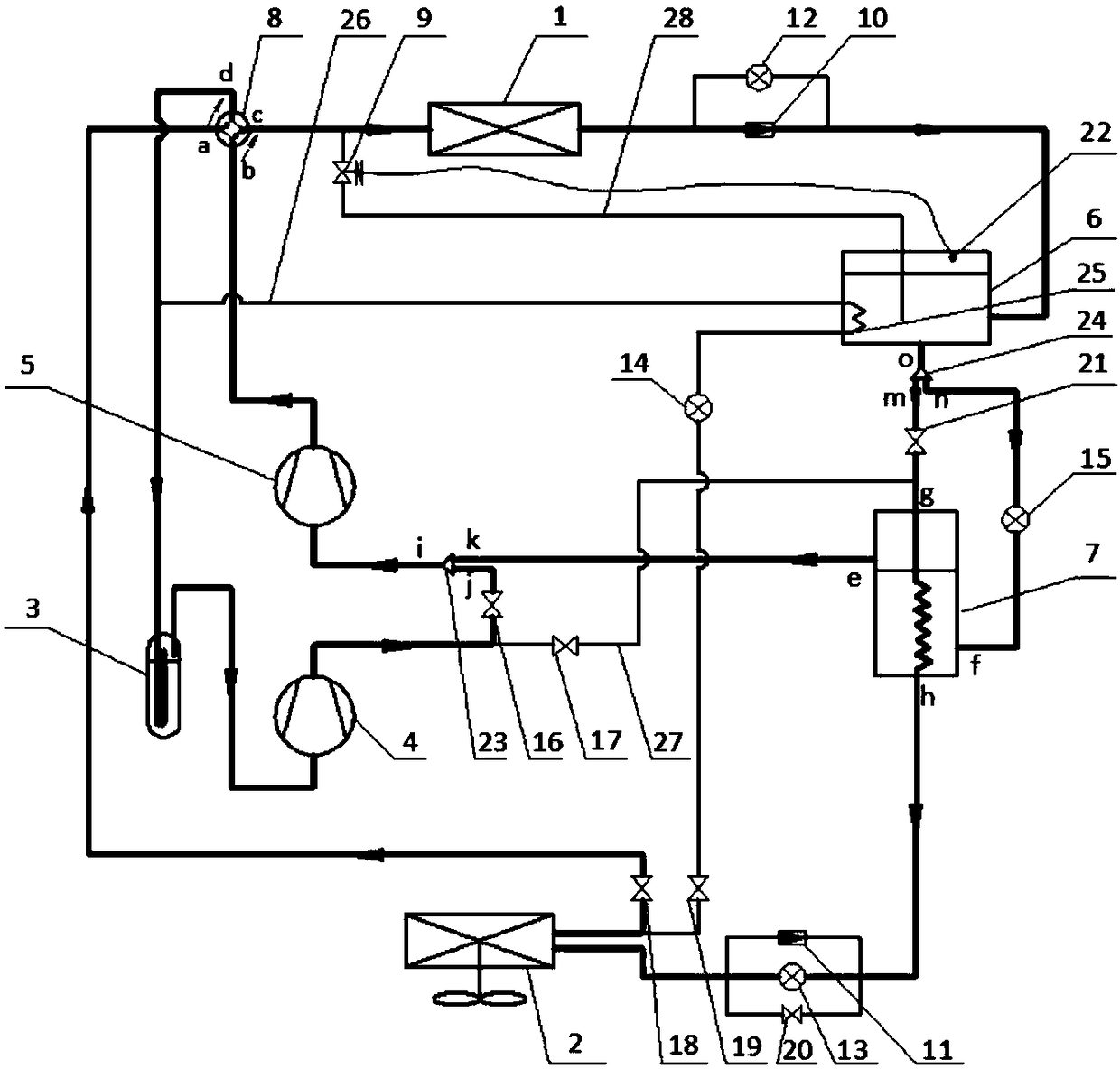
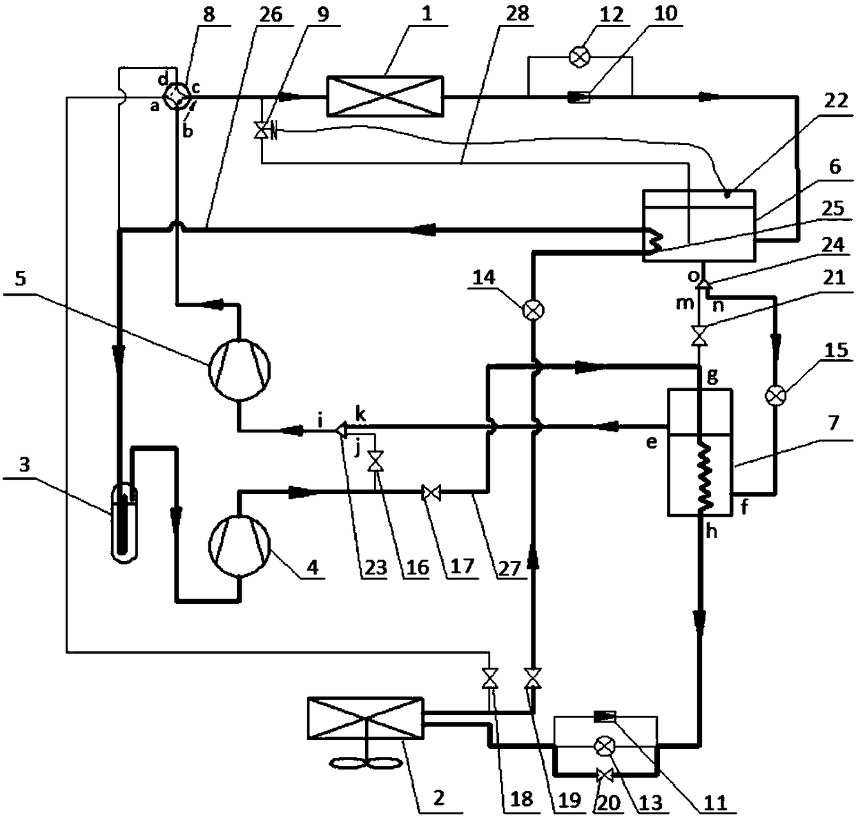
[0033] see figure 1 As shown, the present invention is an air source heat pump defrosting system with two-stage compression switching to partial binary cascade, including an indoor heat exchanger 1, an outdoor heat exchanger 2, a gas-liquid separator 3, a high-pressure liquid reservoir 6, The economizer 7 , the four-way reversing valve 8 , the first defrosting branch 26 , the second defrosting branch 27 and the heating branch 28 .

[0034]One end of the indoor heat exchanger 1 is connected to the first one-way valve 10, and the first one-way valve 10 is connected to the liquid inlet of the high-pressure liquid reservoir 6. The first one-way valve 10 is connected in parallel with the first electronic expansion valve 12, and the high-pressure The outlet of the liquid reservoir 6 is connected to the o end of the liquid splitter 24, the m end of ...


PUM


Abstract

The invention discloses an air source heat pump defrosting system with two-stage compression switching to partial binary cascade, including an indoor heat exchanger, an outdoor heat exchanger, a gas-liquid separator, a compressor, a high-pressure liquid storage device, and a four-way reversing valve, economizer, cut-off valve, defrosting branch and heating branch; the two ends of the first defrosting branch are respectively connected to the entrance of the outdoor heat exchanger and the gas-liquid separator; the two ends of the second defrosting branch The two ends are respectively connected to the exhaust port of the low-pressure compressor and the inlet of the economizer cooling coil; one end of the heating branch is connected to the four-way reversing valve, and the other end is directly connected to the liquid phase of the high-pressure liquid receiver, and the heating solenoid valve is installed on the branch , the supplemental heat sensor is placed in the liquid phase of the high-pressure accumulator. The invention modifies the flow of the two-stage compression system, which can realize the simultaneous operation of heating and defrosting, the heating capacity does not decay, the working condition of the compressor does not change, the impact on the system is small, and the energy consumption is reduced. On the premise of ensuring indoor comfort Achieve high efficiency and energy saving.

Description

technical field [0001] The invention relates to the technical field of air conditioner defrosting, in particular to an air source heat pump defrosting system. Background technique [0002] Air source heat pumps have the advantages of energy saving, environmental protection, and can be used around the clock. However, frosting is common in cold climates. Therefore, after the air conditioner has been running for a period of time, the outdoor unit must switch to the defrosting mode for defrosting. The compressor cannot be used at the same time. Heating, which can seriously affect the temperature in the room. [0003] Several defrosting technologies currently used in air source heat pump units, for example: four-way reversing valve reverse defrosting technology has the disadvantages of large impact on the system, affecting indoor temperature and human comfort; hot gas bypass defrosting technology has disadvantages The defrosting speed is slow and the working condition of the com...

Claims


Application Information

Patent Timeline
Patent Type & Authority Patents(China)
IPC IPC(8): F25B47/02F25B41/00F25B41/40
CPCF25B47/02F25B41/40
Inventor 蒲亮孙福涛齐迪
Owner 江苏辛普森新能源有限公司
Learn More