Verifying device for V-shaped splint manganese alloy glass of handle platen debris recoverer

A technology of inspection device and recycler, which is applied to measurement devices, instruments, scientific instruments, etc., can solve the problems of long time consumption, inconvenient operation, splashing glass fragments, etc. Effect

Inactive Publication Date: 2016-10-12
张志雄
View PDF4 Cites 0 Cited by
  • Summary
  • Abstract
  • Description
  • Claims
  • Application Information

AI Technical Summary

Problems solved by technology

This method is not only inconvenient to operate, it takes a long time, and the tape is a disposable product, which is easy to cause waste and pollution, and the tape residue on the test bench must be removed after each test to remove the broken glass, otherwise , the remaining glass fragments will affect the next experimental test operation
At the same time, the adhesive tape is also likely to be broken by the force of the tempered glass explosion, causing the operator to be injured. Therefore, it is very necessary to improve the tempered glass fragment test device
[0005] Chinese patent application number: 2009203050079, tempered glass falling ball test bench, in order to solve the problem of glass shards splashing everywhere when the tempered glass is tested, the method of supporting the frame box is adopted, although the glass shards can be effectively removed, but the reading of the glass shards is inconvenient , and the installation efficiency of continuous multi-piece tempered glass is low

Method used


Image

  • Verifying device for V-shaped splint manganese alloy glass of handle platen debris recoverer
  • Verifying device for V-shaped splint manganese alloy glass of handle platen debris recoverer
  • Verifying device for V-shaped splint manganese alloy glass of handle platen debris recoverer

Examples


Embodiment Construction

[0057] Describe the present invention in detail below in conjunction with accompanying drawing and specific embodiment:

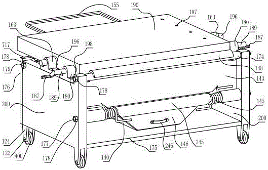
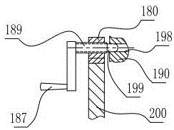
[0058] figure 1 , figure 2 , image 3 , Figure 4 , Figure 5 , Image 6 , Figure 7 , Figure 10 and Figure 12 Among them, the V-shaped splint manganese alloy glass inspection device of the handle platform fragment recovery device, the overall frame includes the support side plates 200 on both sides, the rear shear plate 176 and the bottom shear plate 175, and the support on both sides The upper plane of the side plate 200 is respectively fixed with a table support 163 and a lock pin support 180; the test table 190 has a table rotating shaft 196 on both sides, and the table rotating shaft 196 on both sides is rotatably fixed on the table support 163 respectively. Inside, the upper part of the rear shear plate 176 has a plane 717 on the rear plate, and the plane 717 on the rear plate supports the rear lower plane of the test bench 190; Hole 198; ...


PUM

PropertyMeasurementUnit
Thicknessaaaaaaaaaa

Abstract

The invention relates to a test verifying device for tempered glass and specifically relates to a verifying device for a V-shaped splint manganese alloy glass of a handle platen debris recoverer. As improvement: a platen handle is arranged on a vertical surface at the rear end of a test platen; handle tips at two arc ends of the platen handle are fixedly arranged on the vertical surface at the rear end of the test platen; platen rotating shafts are arranged on the two sides of the test platen; the platen rotating shafts on the two sides are respectively rotatably fixed in a platen support base; a debris recoverer is jointly fixed by a front middle pull rod of a rack, a front upper pull rod of the rack and a rear upper pull rod of the rack; a same-plane V-shaped splint component is fixed on the upper plane of the test platen; a layer of rubber pressing slice is spliced to the slope of the splint; a sliding plate ball is fixed in a stepped hole of a ball base on the upper plane of the plate; an outward extruding spherical surface of the sliding plate ball is in contact with the lower plane of the sliding plate, so that the sliding plate between the lower plane of the sliding plate in one fixing device and the upper plane of the splint in another fixing device is more smooth and easy; the peripheral edges of the tested armorplate glass are uniformly stressed.

Description

technical field [0001] The invention relates to a test and inspection device for tempered glass, in particular to a manganese alloy glass inspection device for a V-shaped splint with a handle plate fragment recovery device that can be enlarged or reduced around the splint and uses a reversible workbench to test the performance index of the glass. . Background technique [0002] China's other patent application number: 201420595067.X, tempered glass fragment state test device, proposed some new methods and measures to deal with brittle glass splints, but it is still impossible to adjust the size at will, and it is impossible to make the four sides of the splints all in the same on flat surface. At least one side in this patent must not be in contact with the test workbench. What is referred to as the suspended retaining wall 5 in the embodiment cannot be in contact with the base 1 simultaneously with other three-side retaining walls, so the retaining piece 4 has to be use...

Claims


Application Information

Patent Timeline
IPC IPC(8): G01N3/30G01N3/04
CPCG01N3/04G01N3/30G01N2203/0039G01N2203/0087G01N2203/04
Inventor 张志雄
Owner 张志雄
Why Eureka
Try Eureka