
Optic camouflage device and manufacturing method therefor

An optical and optical fiber technology, which is applied in the field of optical cloaking devices and its preparation, can solve unavoidable problems, achieve the effects of reducing reflection and scattering, wide application range, and facilitating entry

Inactive Publication Date: 2016-10-12
HUNAN METALLURGY MATERIAL RES INST
View PDF2 Cites 4 Cited by
  • Summary
  • Abstract
  • Description
  • Claims
  • Application Information

AI Technical Summary

Problems solved by technology

These patents provide the advantages and benefits of their respective methods, but they still cannot avoid the common disadvantages of such methods, such as the need for continuous power supply, the need to install numerous small displays, and the need to know the observer's viewing angle in advance.

Method used


Image

  • Optic camouflage device and manufacturing method therefor
  • Optic camouflage device and manufacturing method therefor

Examples


Embodiment Construction

[0017] Embodiments of the present invention will be described in detail below in conjunction with the accompanying drawings.

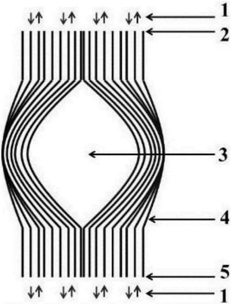
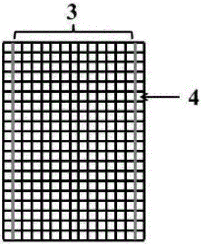
[0018] see Figure 1 to Figure 2 , the present invention provides a first aspect of the present invention provides an optical cloaking device, including a plurality of tightly parallel and bonded total reflection optical fibers 4 and a storage space 3 formed by bending the middle part of the total reflection optical fibers 4, the storage Human bodies or objects can be hidden in the space 3, and the two ends of the total reflection optical fiber 4 across the storage space 3 are aligned, that is, the front end 2 of the total reflection optical fiber and the rear end 5 of the total emission optical fiber are aligned.

[0019] The diameter of the total reflection optical fiber 4 is 0.01-0.5 mm, so that its imaging resolution is higher than that of the naked eye.

[0020] The preparation method of described optical cloaking device comprises the steps:

[...


PUM


Abstract

The invention discloses an optical cloaking device and a preparation method thereof. The optical cloaking device comprises a plurality of tightly parallel and bonded total reflection optical fibers and a storage space formed by bending the middle part of the total reflection optical fiber. A human body or an object can be hidden, and the two ends of the total reflection optical fiber straddling the storage space are arranged in alignment. When preparing, first select a plurality of total reflection optical fibers with a diameter of 0.01-0.5 mm; then bend the middle part of the total reflection optical fiber; then closely adhere a plurality of total reflection optical fibers bent in the middle in parallel, and the curved part forms a storage space . The present invention adopts the fully reflective optical fiber tightly parallel and bonded, which guarantees the stealth technology and effect and does not require external energy, and has a wide range of applications; the optical fiber has a total reflection effect, and the corresponding scene behind the device can be seen at any angle; the total reflection The two ends of the optical fiber are arranged in alignment, which can reduce the reflection and scattering of light, and facilitate the entry, transmission and clear imaging of light.

Description

technical field [0001] The invention relates to the field of optical cloaking, in particular to an optical cloaking device and a preparation method thereof. Background technique [0002] Invisibility has always been a human dream. In recent years, stealth stealth technology has been gradually used. However, most of the stealth and stealth technologies in the field of military industry and national defense are radar stealth rather than optical stealth. In the civilian field, most of the stealth technologies we use are the method of using a camera to capture the scene on the back and then display it on the front of the display, such as Chinese patents 2009202226191, 2014101429565, and 2014200133371. These patents provide the advantages and benefits of their respective methods, but they still cannot avoid the common disadvantages of such methods, such as the need for continuous power supply, the need to install numerous small displays, and the need to know the view angle of t...

Claims


Application Information

Patent Timeline
Patent Type & Authority Applications(China)
IPC IPC(8): G02B6/06
CPCG02B6/06
Inventor 周康宁闵小兵储志强刘东华卢静张彬娟向妍妍
Owner HUNAN METALLURGY MATERIAL RES INST
Learn More