
Passive residual heat removal circulating performance testing system and method

A passive waste heat and test system technology, applied in the field of nuclear reactors, can solve the problems of test verification and no test system, and achieve the effect of ensuring accuracy

Active Publication Date: 2016-10-12
HEFEI GENERAL MACHINERY RES INST
View PDF7 Cites 11 Cited by
  • Summary
  • Abstract
  • Description
  • Claims
  • Application Information

AI Technical Summary

Problems solved by technology

At present, the research on the performance of the passive waste heat removal cycle only has numerical simulation and theoretical analysis, and there is no test system to test and verify its performance.

Method used


Image

  • Passive residual heat removal circulating performance testing system and method
  • Passive residual heat removal circulating performance testing system and method
  • Passive residual heat removal circulating performance testing system and method

Examples


Embodiment 1

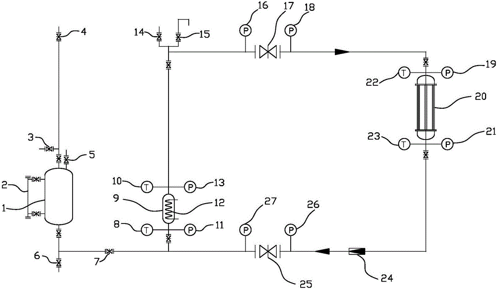
[0036] Such as figure 1 As shown, the passive waste heat removal cycle performance test system includes a waste heat removal cycle simulation system and a supersaturation pressure system, wherein the waste heat removal cycle simulation system includes an internal heat source simulation module and an external heat dissipation module, and the internal heat source simulation module . The external heat dissipation modules are connected through pipelines to form a cyclic test loop, and the supersaturated pressure system makes the internal pressure of the test system exceed the saturated vapor pressure of the circulating liquid at the test temperature. The in-core heat source simulation module of the present invention is used to simulate the heat source in an actual nuclear reactor. The in-core heat source simulation module and the out-of-core heat dissipation module together constitute a passive residual heat discharge cycle test system. By monitoring the cycle in the cycle test loo...

Embodiment 2

[0043] The test method of the passive waste heat removal cycle performance test system includes the following steps:

[0044] S1. Preparation before the test: open the first exhaust valve 14, the communication valve 7, the first resistance valve 17, the second resistance valve 25, and the second exhaust valve 4, and exhaust the residual heat through the filling valve 6 to simulate the circulation system 1. Fill the pressure storage tank 1 with water until the water overflows from the first exhaust valve 14 and the second exhaust valve 4, and turn on the electric heater 12 to slowly heat the water in the pressure storage tank 9, so that the water in the circulation test circuit At the same time, monitor the temperature at the outlet end of the pressure storage tank 9, and control the temperature at the outlet end of the pressure storage tank 9 by adjusting the heating power of the electric heater 12 to not exceed 85°C until no gas is precipitated in the waste heat discharge cycl...


PUM


Abstract

The invention mainly relates to a passive residual heat removal circulating performance testing system. The passive residual heat removal circulating performance testing system comprises a residual heat removal circulating simulation system and an oversaturated pressure system, wherein the residual heat removal circulating simulation system comprises an in-pile heat source simulation module and an out-pile heat dissipation module; the in-pile heat source simulation module and the out-pile heat dissipation module are communicated through a pipeline to from a circulating testing loop; and the oversaturated pressure system enables pressure in the testing system to exceed saturated steam pressure of circulating liquid at a testing temperature. The in-pile heat source simulation module is used for simulating a heat source in an actual nuclear reactor; the volume flow of circulating liquid in the circulating testing loop, temperatures of inlet and outlet ends of the in-pile heat source simulation module and temperatures of inlet and outlet ends of the out-pile heat dissipation module are monitored so that the performance of the residual heat removal circulating simulation system can be obtained; and performances of the residual heat removal circulating simulation system actually arranged in the nuclear reactor can be tested in an accident process according to a performance testing result.

Description

technical field [0001] The invention belongs to the technical field of nuclear reactors, and in particular relates to a passive residual heat discharge cycle performance test system and a test method. Background technique [0002] Nuclear energy is a clean, economical source of energy, usually safe, but in the event of an accident, it would be catastrophic. In order to improve the inherent safety of the reactor and reduce the probability of core meltdown in the event of an accident, the third-generation nuclear energy application introduces a passive waste heat removal circulation system. In the case of no external power source, the natural circulation established in the loop will The heat inside the reactor is exhausted to keep the reactor safe. [0003] The performance of the passive waste heat removal circulation system is affected by factors such as the temperature difference between the internal heat source and the external cooling source, the heat dissipation power of...

Claims


Application Information

Patent Timeline
Patent Type & Authority Applications(China)
IPC IPC(8): G21C17/02
CPCG21C17/02Y02E30/30
Inventor 陈永东倪利刚吴晓红于改革刘孝根
Owner HEFEI GENERAL MACHINERY RES INST
Learn More