Laser annealing equipment

A laser annealing and equipment technology, applied in electrical components, semiconductor/solid-state device manufacturing, circuits, etc., can solve the problems of high manufacturing cost, low alignment accuracy, long cycle, etc., to reduce equipment cost and time investment, improve The effect of alignment accuracy

Active Publication Date: 2016-10-12
BOE TECH GRP CO LTD +1
View PDF5 Cites 4 Cited by
  • Summary
  • Abstract
  • Description
  • Claims
  • Application Information

AI Technical Summary

Problems solved by technology

[0008] The present invention aims at the above-mentioned deficiencies in the prior art, and provides a laser annealing equipment, which is used to at least partially solve the problems of low alignment accuracy, low production capacity, high manufacturing cost and long cycle time of the existing MLA annealing equipment

Method used


Image

  • Laser annealing equipment
  • Laser annealing equipment

Examples


Embodiment Construction

[0032] The technical solutions in the present invention will be clearly and completely described below in conjunction with the accompanying drawings in the present invention. Apparently, the described embodiments are part of the embodiments of the present invention, not all of them. Based on the embodiments of the present invention, all other embodiments obtained by persons of ordinary skill in the art without making creative efforts belong to the protection scope of the present invention.

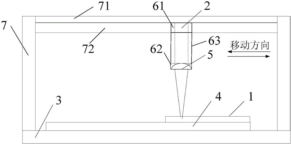
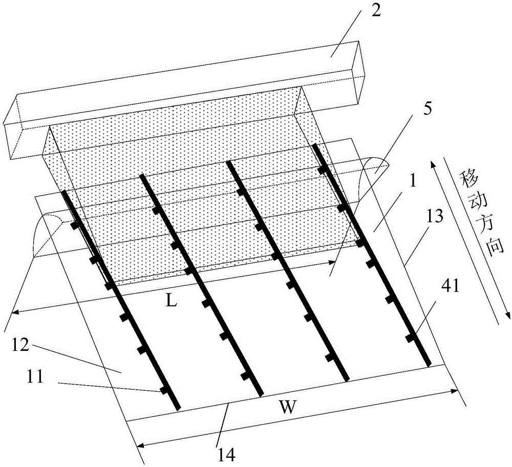
[0033] Combine the following figure 1 and figure 2 , detailing the structure of the laser annealing equipment of the present invention.

[0034] The invention provides a laser annealing device, which includes a mask plate 1 and a laser source 2, and the laser source 2 is used to generate an excimer laser beam. Excimer laser refers to the laser generated when the molecules formed by the mixture of inert gas and halogen gas excited by the electron beam transition to their ground state. In...


PUM


Abstract

The invention provides laser annealing equipment. A lens is arranged between a laser source and a mask plate to conduct convergence on quasimolecule laser beams generated by the laser source, an equipment light path is changed, the laser source and the lens conduct synchronous and horizontal movement along the mask plate, the mask plate is scanned through the converged quasimolecule laser beams, the converged quasimolecule laser beams are transmitted to an annealing area of an array substrate through the light-transmitting area of the mask plate, and laser annealing is achieved. In the laser annealing process, the mask plate always covers the array substrate and cannot move along with the laser source and the lens, alignment precision can be improved, patterns on the substrate do not need to be tracked in real time, and thus the precision requirement of the high-PPI substrate can be met without influencing capacity; besides, according to the laser annealing equipment, an ordinary lens replaces a micro lens array, the lens can be suitable for array substrates of all models, and thus cost investment and time investment of the equipment are lowered.

Description

technical field [0001] The invention relates to the field of display technology, in particular to a laser annealing device. Background technique [0002] At present, the laser annealing (ELA) of the LTPS (Low Temperature Poly-silicon, low temperature polysilicon technology) production line is to perform laser annealing on the a-Si on the entire glass substrate after the deposition of a-Si (amorphous silicon). After ELA, all a-Si on the surface of the glass substrate is converted to p-Si (polysilicon), in order to ensure the source (S), drain (D) and p-Si ohmic contact, SD Doping (doping) process is required , and the doping process requires the purchase of expensive doping equipment and the transformation of special gas pipelines, etc., which requires a large investment in equipment. In addition, the LTPS process is complex and it is difficult to ensure large-area uniformity, and it is difficult to achieve large-scale product production. Therefore, the latest MLA (microlens...

Claims


Application Information

Patent Timeline
IPC IPC(8): H01L21/268
CPCH01L21/268
Inventor 裴晓光赵海生林金升肖志莲
Owner BOE TECH GRP CO LTD
Why Eureka
Try Eureka