A control method for synchronous closing and grid-connection of microgrid group

A technology of micro-grid group and control method, which is applied in the direction of single-network parallel feeding arrangement, etc., can solve the problems of large closing impulse current, poor adjustment accuracy, and large impulse current, and achieve high adjustment accuracy, fast adjustment speed, and reduced impact effect

Active Publication Date: 2022-06-21
CHINA ELECTRIC POWER RES INST +2
View PDF6 Cites 0 Cited by
  • Summary
  • Abstract
  • Description
  • Claims
  • Application Information

AI Technical Summary

Problems solved by technology

[0005] 1) In the synchronous closing device of the digital substation, the frequency is basically not adjustable, but due to the frequency difference between the power sources, it is necessary to wait for the phase difference to be zero before realizing grid connection, which takes a long time, usually several minutes; in addition, It is necessary to consider the influence of signal communication time, circuit breaker closing time, signal sampling time, data processing time, etc. on synchronous closing. The calculation is complex and inaccurate, resulting in a large closing impulse current
[0006] 2) In the synchronous grid-connected device of the synchronous generator in the power plant, although the synchronous generator can adjust the output voltage amplitude by adjusting the excitation current, adjust the governor to adjust the output frequency, but the adjustment accuracy is poor, resulting in the grid side and the generator side When the frequency and phase of the system cannot be strictly equal to the grid, it is necessary to use the synchronous point forecasting algorithm, which still has the disadvantages of long time consumption, complicated calculation, and large inrush current

Method used


Image

  • A control method for synchronous closing and grid-connection of microgrid group
  • A control method for synchronous closing and grid-connection of microgrid group
  • A control method for synchronous closing and grid-connection of microgrid group

Examples


Embodiment Construction

[0027] The technical solution of the present invention will be described in further detail below in conjunction with the accompanying drawings.

[0028] The frequency / phase adjustment accuracy of the traditional synchronous generator is poor. When the frequency and phase of the grid side and the generator side are not strictly equal to the grid, the synchronous point forecast algorithm has to be used, which still has long time consumption, complicated calculation, and inrush current. Big downside. The invention provides a method for synchronous closing and grid-connection control of a micro-grid group, which makes full use of the advantages of easy adjustment of the output voltage frequency / phase of the micro-grid power generation unit of the power electronic interface, and realizes fast synchronous grid-connection, which usually only takes a few seconds , The current impact is small.

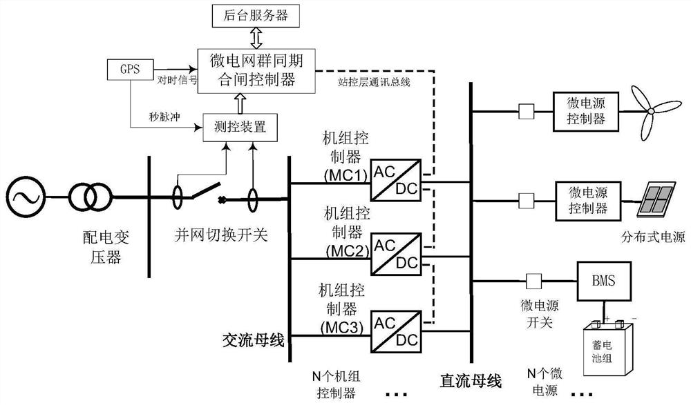
[0029] like figure 1 As shown, the microgrid group of the present invention includes a pl...


PUM


Abstract

The invention provides a control method for synchronous closing and grid-connection of a microgrid group, which includes: respectively measuring the voltage amplitude, voltage frequency and voltage phase difference on the side of the distribution network and the side of the microgrid group with a voltage transformer; The voltage and frequency set the output voltage and frequency target value of the AC / DC conversion unit on the microgrid group side; the communication bus sends a broadcast message to the AC / DC conversion unit; after a predetermined time, the phase-locked loop follows the frequency and phase of the distribution network side output voltage frequency; the communication bus sends a broadcast message to the AC / DC conversion unit; and the synchronous closing controller of the microgrid group sends a closing command. The grid-connected frequency is controlled by the inverter based on the power electronic interface control provided by the present invention, so that the voltage amplitude, frequency and phase of the microgrid side and the distribution network side are exactly the same, the adjustment accuracy is high, and the impact of closing surge current is reduced .

Description

technical field [0001] The invention relates to the field of new energy power generation, in particular to a control method for simultaneous closing and grid-connection of micro-grid groups. Background technique [0002] With the development of micro-grid technology matures, there are reliable utilization methods to balance regional distribution network load locally, improve power supply reliability, and increase the utilization rate of renewable energy. However, due to the limitation of the capacity of a single micro-grid, its acceptance is intermittent There is a limit to the number of sexual power sources. With the increase of the penetration rate of intermittent power in the regional distribution network, the external grid connected to it will bear the power fluctuations in the distribution network, which may lead to the phenomenon of abandoning wind and light. The power grid forms a micro-grid group to reduce power fluctuations in the distribution network to a certain ...

Claims


Application Information

Patent Timeline
Patent Type & Authority Patents(China)
IPC IPC(8): H02J3/46
CPCH02J3/46
Inventor 盛万兴刘科研孟晓丽贾东梨何开元胡丽娟叶学顺刁赢龙唐建岗董伟杰李雅洁
Owner CHINA ELECTRIC POWER RES INST
Why Eureka
Try Eureka