Remote CCD light-control technology based photovoltaic charging pile

A charging pile and technology technology, applied in the direction of collectors, electric vehicles, electrical components, etc., can solve the problems of wasting energy, damage to electrical equipment, short service life of charging piles, etc., to reduce production costs, improve power generation efficiency, and charge fairness. reasonable effect

Inactive Publication Date: 2016-10-12
SUZHOU ZEMST MACHINERY CO LTD
View PDF11 Cites 7 Cited by
  • Summary
  • Abstract
  • Description
  • Claims
  • Application Information

AI Technical Summary

Problems solved by technology

However, the charging piles have been placed outdoors for a long time. Due to the rapid development of the city, some drainage systems have not been upgraded. After the heavy rain, the water in the roads has caused damage to some urban electrical equipment, which is easily corroded by air and water. After the single-layer shell is corroded , it is easy to damage the internal components. In addition, the existing charging piles are generally installed outdoors. Once an emergency power failure occurs in the city, it is easy to damage the circuit and electric vehicles; For piles, it is easy to be powered by the city; there are still some charging piles that use solar energy for power supply, but the current solar charging piles often have a low utilization rate of solar energy, and the body of the charging pile is placed in strong light for a long time Under the circumstances, the service life of the charging pile will also be shortened; the existing charging piles generally only serve cars, and the charging time is relatively long, and the long-term use of its electronic components generates more heat, and usually requires special cooling equipment, such as Traditional compressor refrigeration equipment is used, which consumes a lot of energy and wastes energy; and the existing outdoor self-service payment charging piles generally adopt the method of paying first and then charging, which has the disadvantage of not charging strictly according to the charging amount, and cannot effectively adapt to market development. needs

Method used


Image

  • Remote CCD light-control technology based photovoltaic charging pile
  • Remote CCD light-control technology based photovoltaic charging pile

Examples


Embodiment Construction

[0032] The following will clearly and completely describe the technical solutions in the embodiments of the present invention with reference to the accompanying drawings in the embodiments of the present invention. Obviously, the described embodiments are only some, not all, embodiments of the present invention. Based on the embodiments of the present invention, all other embodiments obtained by persons of ordinary skill in the art without making creative efforts belong to the protection scope of the present invention.

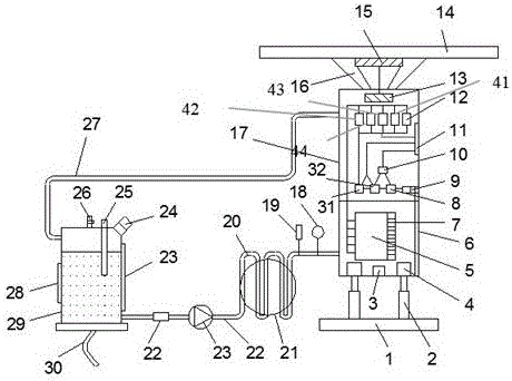
[0033] see Figure 1~2 , in an embodiment of the present invention, a photovoltaic charging pile based on remote CCD light control technology, including a charging housing, a cooling cycle device, a signal modulation control device, an LED lamp, a receiving antenna, a light detector, and a signal processing circuit, the One side of the charging housing 17 is provided with a display screen 11 and a closing door 6, and the charging housing 17 is provided with an...


PUM


Abstract

Disclosed is a remote CCD light-control technology based photovoltaic charging pile. The photovoltaic charging pile comprises a charging shell and a cooling circulating apparatus, wherein a display screen and a closed door are arranged on one side of the charging shell; an intelligent lock, an intelligent lock control apparatus, an optical detector, a payment apparatus, a billing apparatus, multiple electric energy meters and a charging apparatus are arranged in the charging shell; the display screen is connected with the optical detector, the payment apparatus, the billing apparatus and the multiple electric energy meters separately; the intelligent lock is connected with the closed door and the intelligent lock control apparatus separately; the intelligent lock control apparatus is connected with the optical detector and the payment apparatus; the payment apparatus is connected with the billing apparatus; the billing apparatus is connected with the multiple electric energy meters; and the output end of each electric energy meter is connected with the charging apparatus. The photovoltaic charging pile is effectively waterproof; the solar automatic power generation efficiency is high; and meanwhile, the photovoltaic charging pile is reasonable in charging, high in intelligent degree, capable of realizing effective radiating on the internal electronic parts, low in cost, low in energy consumption, and long in service life.

Description

technical field [0001] The invention relates to the technical field of chargers, in particular to a photovoltaic charging pile based on remote CCD light control technology. Background technique [0002] At present, energy conservation, environmental protection, and low-carbon life are hot topics. In order to achieve emission reduction goals, the country vigorously promotes electric bicycles and electric vehicles. Among them, the electric vehicle itself has no pollution, does not emit carbon dioxide, and has no tail gas pollution. It has the advantages of energy saving and environmental protection for ordinary cars with high carbon dioxide emissions. At the same time, it is quite beneficial to control environmental pollution and reduce exhaust emissions. Electricity can be obtained from a variety of energy sources, such as thermal power, hydropower, wind power, and solar energy, which have the advantage of a wide range of sources. [0003] At present, there are a variety of ...

Claims


Application Information

Patent Timeline
Patent Type & Authority Applications(China)
IPC IPC(8): H02J7/00H05K7/20
CPCH02J7/0042H05K7/20281
Inventor 王烨
Owner SUZHOU ZEMST MACHINERY CO LTD
Why Eureka
Try Eureka