Building garbage crusher

A technology of construction waste and pulverizer, which is applied in the direction of grain processing, separation of dispersed particles, chemical instruments and methods, etc., can solve the problems of low waste utilization rate, environmental pollution, and lack of pertinence, so as to improve waste utilization rate and reduce production Low cost and good crushing effect

Inactive Publication Date: 2016-10-26
HUANGHE S & T COLLEGE
View PDF6 Cites 14 Cited by
  • Summary
  • Abstract
  • Description
  • Claims
  • Application Information

AI Technical Summary

Problems solved by technology

With the reconstruction of old cities, the demolition of villages in the city, and the reconstruction of roads, there are more and more construction wastes. However, most construction wastes are transported to the suburbs or villages by construction units without any treatment, and are piled up in the open air or landfilled, consuming a lot of waste. Construction funds such as land requisition, garbage removal and transportation fees, etc. At the same time, problems such as dust and dust flying during the removal and stacking process have caused serious environmental pollution; at present, in the field of construction waste resource regeneration, construction waste has been treated After the recycled aggregate is generated, it can be used as recycled concrete. The quality of recycled aggregate restricts the quality of recycled concrete. The quality of recycled concrete can be greatly improved by peeling off the sundries in the recycled aggregate and the sticky powder on the surface. At present, there is no targeted equipment in the field of renewable resources to remove surface-adhesive powders. Usually, impact crushers are used to treat surface-adhesive powders. Generate more dust, pollute the environment and waste raw materials

Method used


Image

  • Building garbage crusher
  • Building garbage crusher
  • Building garbage crusher

Examples


Embodiment Construction

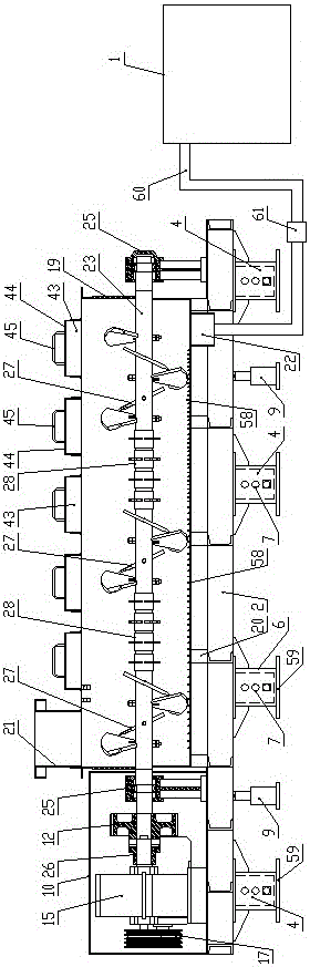
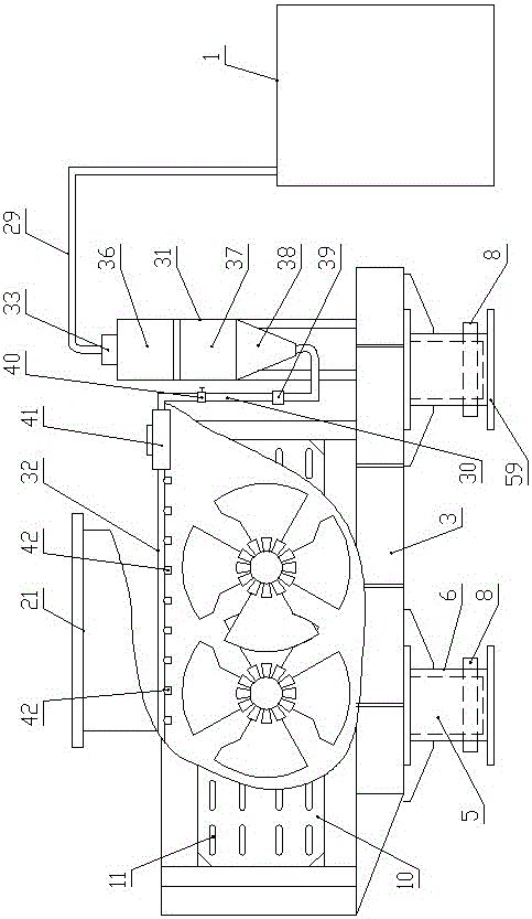
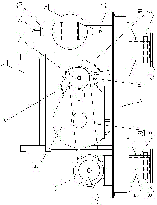
[0030] Such as Figure 1-9 As shown, a construction waste pulverizer of the present invention includes a frame, a power drive system is provided at the left end of the frame, and the power output end of the power drive system is connected with a material crushing system located on the right side of the power drive system. The system is fixed on the frame, which is equipped with an automatic spraying and dust suppression system located in front of the material crushing system feeding place. The spraying part of the automatic spraying and dust suppression system is located in the material crushing system, and a sedimentation tank is installed on one side of the frame. 1.

[0031] The frame includes two longitudinal beams 2 parallel to each other. The two longitudinal beams 2 are arranged along the left and right horizontal directions. A number of beams 3 are evenly spaced between the two longitudinal beams 2 along the length direction. The lower surfaces of the two longitudinal ...


PUM


Abstract

The invention discloses a building garbage crusher which comprises a rack, wherein the left end part of the rack is provided with a power drive system; the power output end of the power drive system is in transmission connection to a material crushing system positioned at the right side of the power drive system; the material crushing system is fixed to the rack; an automatic spraying and dust-reducing system in front of a charging part of the material crushing system is arranged on the rack; a spraying part of the automatic spraying and dust-reducing system is positioned in the material crushing system; and one side of the rack is provided with a settling tank. According to the building garbage crusher disclosed by the invention, synchronous drive of a primary transmission shaft and a secondary transmission shaft is realized through the power drive system, dust generated in a crushing process is effectively reduced through the automatic spraying and dust-reducing system, cyclic utilization of water flow is realized, and material crushing is realized through the material crushing system, so that building garbage is recycled; and the building garbage crusher is simple to operate, is stable in work, is good in crushing effect, increases a waste utilization rate, reduces production cost, and is energy-saving and environmentally friendly.

Description

technical field [0001] The invention belongs to the technical field of construction waste treatment equipment, in particular to a construction waste shredder. Background technique [0002] Construction waste refers to the dregs, spoils, waste materials, residual mud and other wastes produced during the construction, laying or demolition, and repair of various buildings, structures, and pipe networks by construction units or individuals. The main components of construction waste are bricks, sand and gravel, and lower house soil. With the reconstruction of old cities, the demolition of villages in the city, and the reconstruction of roads, there are more and more construction wastes. However, most of the construction wastes are transported to the suburbs or villages by construction units without any treatment, and are piled up in the open air or landfilled, consuming a lot of waste. Construction funds such as land requisition, garbage removal and transportation fees, etc. At ...

Claims


Application Information

Patent Timeline
Patent Type & Authority Applications(China)
IPC IPC(8): B02C13/20B02C13/26B02C13/28B02C13/30B02C13/282B02C18/14B02C18/18B01D47/06
CPCB01D47/06B02C13/20B02C13/26B02C13/28B02C13/282B02C13/30B02C18/142B02C18/18B02C2013/2812
Inventor 刘朝中王红祝林林
Owner HUANGHE S & T COLLEGE
Why Eureka
Try Eureka