Eureka AIR delivers breakthrough ideas for toughest innovation challenges, trusted by R&D personnel around the world.

Pressurization and pressure relief system installed in integrated manner

A pressure relief and mounting frame technology, which is applied in packaging, valve devices, transportation and packaging, etc., can solve the problems such as difficulty in increasing the pressure relief speed of the pressure relief device, failure to achieve bursting effect, and difficulty in increasing the effective cross-sectional area , to achieve the effect of increasing the pressure relief speed, high efficiency, and increasing the discharge efficiency

Inactive Publication Date: 2016-10-26
TIANZI ENVIRONMENTAL PROTECTION EQUIP MFG TIANJIN
View PDF0 Cites 2 Cited by
  • Summary
  • Abstract
  • Description
  • Claims
  • Application Information

AI Technical Summary

Problems solved by technology

It is difficult to increase the effective cross-sectional area. Due to the limitation of the effective cross-sectional area of ​​the vent, it is also difficult to increase the pressure relief speed of the pressurization and pressure relief device, resulting in the failure of the organic matter treatment to achieve the ideal bursting effect.

Method used


Image

  • Pressurization and pressure relief system installed in integrated manner
  • Pressurization and pressure relief system installed in integrated manner
  • Pressurization and pressure relief system installed in integrated manner

Examples


Embodiment Construction

[0039] The pressurization and pressure relief system of the present invention will be described in detail below in conjunction with the accompanying drawings.

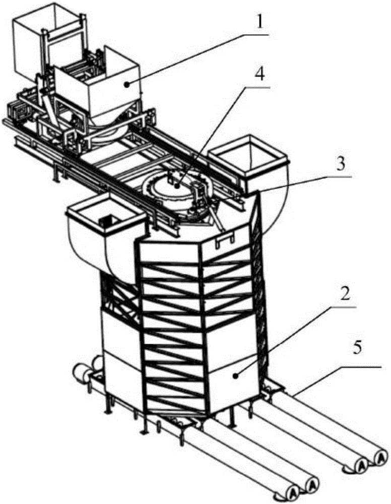
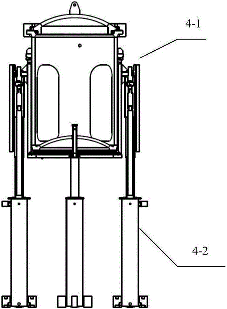
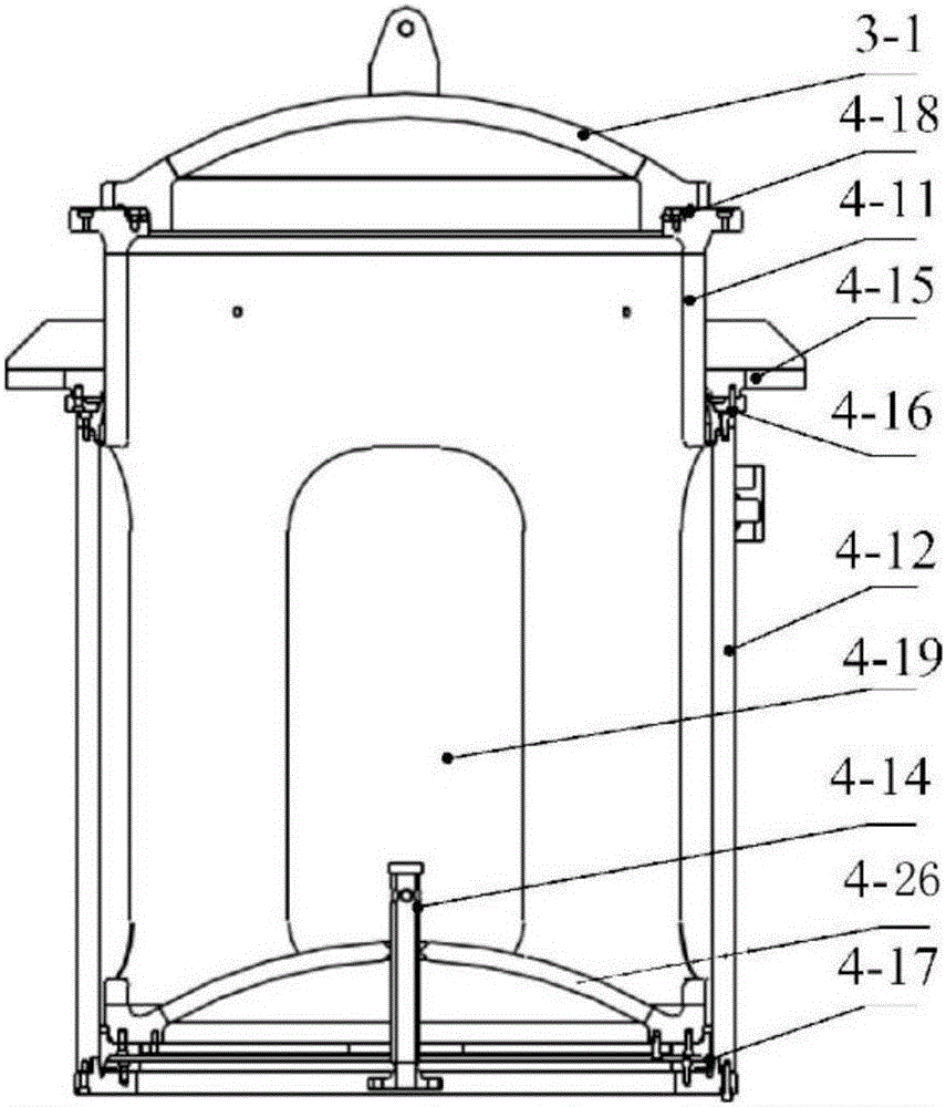
[0040] Such as figure 1 Shown is a schematic structural diagram of the large-diameter organic matter processing equipment. It can be seen from the figure that the large-diameter organic matter processing equipment specifically includes a feeding device 1, a separator 2, a cover opening mechanism 3, a pressurization and pressure relief device 4, and a discharge device 5. The pressure relief device 4 is installed inside the separator 2, the cap opening mechanism 3 and the feeding device 1 are installed on the upper part of the pressure relief device 4, that is, the top of the separator 2, and the discharge device 5 is located below the separator 2 , wherein the feeding device 1 injects the material into the inside of the pressure relief device 4 through the cap opening device 3, the pressure relief device 4 heats and pre...


PUM


Abstract

The invention discloses a pressurization and pressure relief system installed in an integrated manner. A pressurization and pressure relief device is installed on an installing rack and comprises a separate cylinder barrel sealing device and a pneumatic opening mechanism. The separate cylinder barrel sealing device comprises an upper cylinder barrel and a lower cylinder barrel. The lower cylinder barrel is installed on the outer side of the upper cylinder barrel in a sleeving manner. The upper cylinder barrel comprises a steam valve port located in the bottom and discharging openings located in the side portion. The upper cylinder barrel is provided with installing lugs. The lower cylinder barrel is in sliding connection with the upper cylinder barrel. The lower cylinder barrel slides along a guide rail. A sliding block of the guide rail is connected to the installing lugs of the lower cylinder barrel in a screwed manner. The guide rail and the installing rack are welded. The installing lugs of the upper cylinder barrel and the installing rack are connected through bolts. The pneumatic opening mechanism is used for driving the lower cylinder barrel to slide up and down. The installing rack is installed in an integrated manner, the whole pressurization and pressure relief system is compact in structure and overcomes the defect that a traditional pressurization and pressure relief device occupies large space, and the production and use cost is reduced.

Description

technical field [0001] The invention belongs to the field of organic matter treatment, and in particular relates to an integratedly installed pressurization and pressure relief system. Background technique [0002] The main bottleneck of the degassing and pressure relief speed of large container devices is the size of the degassing cross-sectional area. With the traditional degassing valve structure, increasing the caliber and increasing the opening speed are contradictory. Therefore, the pressure relief speed is generally slow and the processing efficiency is low. The problem. Although the cage-type ejection device increases the deflation caliber and pressure relief speed, it has a large load, complex structure, difficult packing, and no protection for the sealing part, low pressure relief efficiency, serious damage to the sealing ring, poor reliability and maintainability, etc. question. [0003] At present, the maximum effective cross-sectional area of ​​the conventiona...

Claims


Application Information

Patent Timeline
Patent Type & Authority Applications(China)
IPC IPC(8): B02C19/18B02C23/04B02C23/00B02C23/02B02C23/08
CPCF16J15/06F16K3/24F16K3/30F16K27/041B65D90/32B65G65/23B02C19/0056B02C19/18B02C23/00B02C23/02B02C23/04B02C23/08B08B5/02B09B3/00B02C2201/06B09B3/45
Inventor 关新华谢甲辰崔承琪张莹
Owner TIANZI ENVIRONMENTAL PROTECTION EQUIP MFG TIANJIN
Why Eureka
Eureka Blog
Learn More