Welding wire winding machine capable of automatically controlling lag angles

A technology of layer winding machine and lag angle, applied in the field of welding wire layer winding machine with automatic control of lag angle, can solve the problems of difficulty in precise control of lag angle and wide diameter range of welding wire, etc. changing effect

Inactive Publication Date: 2016-10-26
武汉科技大学城市学院
6 Cites 12 Cited by

AI-Extracted Technical Summary

Problems solved by technology

This method is suitable for a wide range of welding wire diameters, the error will not accumulate, and the wire stroke...

Method used

3, the left limit switch 2 of this specific embodiment and the right limit switch 11 are correspondingly installed on the near left end and near the right end of the guide rod 6, the installation position of the limit switch can be changed easily, and the wiring The stroke is easy to adjust, so it can adapt to various wire reels of different specifications.
4, the second variable frequency motor 3 that this specific embodiment is used...

Abstract

The invention relates to a welding wire winding machine capable of automatically controlling lag angles. According to the technical scheme, a wire take-up mechanism and a wire arranging mechanism of the welding wire winding machine are arranged in parallel; a first variable-frequency motor (1) of the wire take-up mechanism and a shaft of a wire winding plate (12) of the wire take-up mechanism are connected; two guide rods (6) of the wire arranging mechanism penetrate through corresponding through holes of a mobile platform (7), and a left limit switch (2) and a right limit switch (11) are correspondingly installed at the parts, close to the two ends, of one guide rod (6); a screw rod (5) in threaded connection with the mobile platform (7) is connected to a shaft of a second variable-frequency motor (3), the mobile platform (7) is fixedly connected to the rear end of a swinging strip-shaped plate (9) through a supporting shaft (18), an angular displacement sensor (17) on the mobile platform (7) is fixedly connected to the swinging strip-shaped plate (9) through a connecting rod (16), and guide devices (8) are symmetrically installed at the two ends of the swinging strip-shaped plate (9). The welding wire winding machine has the advantages that error accumulation is small, the adaptation range of the diameters of welding wires is wide, the wire arranging stroke is easy to adjust and control over the lag angles is accurate.

Application Domain

Technology Topic

Image

  • Welding wire winding machine capable of automatically controlling lag angles
  • Welding wire winding machine capable of automatically controlling lag angles
  • Welding wire winding machine capable of automatically controlling lag angles

Examples

  • Experimental program(1)

Example Embodiment

[0031] Example 1
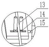
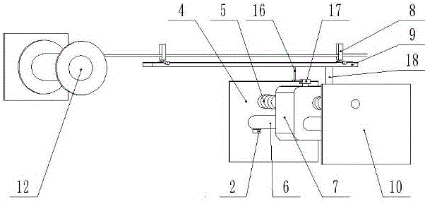
[0032] A welding wire layer winding machine with automatic control of lagging angle. like figure 1 and image 3 As shown, the welding wire layer winding machine is composed of a control system, a wire arranging mechanism and a wire take-up mechanism; the wire take-up mechanism and the wire arranging mechanism are arranged in parallel, and the wire take-up mechanism is located directly in front of the wire arranging mechanism.
[0033] like figure 1 As shown, the wire take-up mechanism is composed of a first frequency conversion motor 1 and a wire winding reel 12, and the first frequency conversion motor 1 is axially connected with the wire winding reel 12 through a shaft coupling.
[0034] like figure 1 and image 3 As shown, the cable arrangement mechanism includes a second variable frequency motor 3 , a lead screw 5 , two guide rods 6 , a moving platform 7 and a swinging strip plate 9 . The body of mobile platform 7 is square, and described body has two through holes horizontally, and two through holes are arranged in parallel, and two guide rods 6 pass through two through holes correspondingly, and the two through holes of two guide rods 6 The end is fixedly connected with the corresponding left mounting frame 4 and the right mounting frame 10, and a left limit switch 2 and a right limit switch 11 are correspondingly housed near the left end and the right end of a guide rod 6. There are screw holes above or below the two through holes of the body, the center line of the screw hole is parallel to the center line of the two through holes, the lead screw 5 is threadedly connected with the screw holes, and one end of the lead screw 5 is installed through a bearing In the right mounting frame 10, the other end of the leading screw 5 passes through the bearing installed in the left mounting frame 4 and is connected with the second frequency conversion motor 3 shafts.
[0035] like image 3 As shown, there is a shaft hole vertically at the middle position on the rear side of the upper plane of the body, the lower end of the support shaft 18 is movably loaded into the shaft hole, and the upper end of the support shaft 18 is close to the lower plane of the swing strip plate 9 The end is fixedly connected; the upper plane of the body is equipped with an angular displacement sensor 17, the angular displacement sensor 17 is located directly in front of the shaft hole, and the rotating part of the angular displacement sensor 17 is fixed to the lower plane of the swing strip plate 9 through the connecting rod 16 connect.
[0036] like figure 1 and image 3 As shown, there are strip grooves symmetrically near the front end and the rear end of the upper plane of the swing strip plate 9, the strip grooves are parallel to the short sides of the swing strip plate 9, and each strip groove is equipped with Guide 8. The structures of the two guides 8 are identical: as figure 2As shown, the guide 8 includes two sliding seats 14, two rollers 13 and an adjusting bolt 15; the two sliding seats 14 are square, and the two sliding seats 14 are movably loaded into the bar-shaped grooves. ; The two slides 14 respectively have screw holes, the thread direction of the screw holes of the two slides 14 is opposite, and the extension lines of the centerlines of the screw holes of the two slides 14 are the same straight line. The adjusting bolt 15 passes through the strip groove and is threadedly connected with the screw holes of the two slide seats 14, and the upper planes of the two slide seats 14 are respectively equipped with rollers 13, and the two rollers 13 are vertically arranged; The structure is the same: the circular sleeve is movably connected with the vertical shaft through the bearing, and the vertical shaft is vertically fixed on the sliding seat (upper plane of 14).
[0037] The control system includes a PLC 20 , a first frequency converter 24 , a second frequency converter 22 and a touch screen 21 . like Figure 4 As shown, the L terminal and N terminal of PLC20 are connected to the L phase and N of 220V AC 19 correspondingly, the I0.0 terminal of PLC20 is connected to the NO terminal of left limit switch 2, and the I0.1 terminal of PLC20 is connected connected to the NO terminal of the right limit switch 11; the AIW0 terminal of the PLC20 is connected to the 2 terminal of the angular displacement sensor 17; the RS485 communication port of the PLC20 is connected to the RS485 communication port of the touch screen 21; the Q0.0 terminal of the PLC20 , Q0.1 terminal, AQW4 terminal are correspondingly connected with the D0 terminal, D1 terminal, and AC terminal of the first inverter 24; the Q0.4 terminal, Q0.5 terminal, and AQW6 terminal of the PLC20 are connected with the first The D0 terminal, D1 terminal, and AC terminal of the second frequency converter 22 are connected correspondingly; the R terminal, S terminal, and T terminal of the first frequency converter 24 are connected to the A terminal, B terminal, and C The terminals are correspondingly connected, the R terminals, S terminals, and T terminals of the second frequency converter 22 are connected with the A terminals, B terminals, and C terminals of the second variable frequency motor 3, and the U terminals of the three-phase AC power supply 23 are connected correspondingly. The phase, V phase and W phase are connected to the U terminal, V terminal and W terminal of the first frequency converter 24 and the U terminal, V terminal and W terminal of the second frequency converter 22 respectively.
[0038] Compared with the prior art, this specific embodiment has the following positive effects:
[0039] 1. The control system of this specific embodiment adopts a touch screen 21, which can conveniently modify parameters such as lag angle and winding speed.
[0040] 2. The structure of the guide 8 adopted in this specific embodiment is: two square sliding seats 14 are movably arranged in each strip groove, and the two sliding seats 14 are horizontally provided with screw holes along the same center line , the screw holes of the two sliding seats 14 are threaded in the opposite direction; the adjusting bolt 15 passes through the strip groove and is threadedly connected with the screw holes of the two sliding seats 14, and the upper plane of each sliding seat 14 is movably equipped with two rollers 13 . Rotating the adjusting bolt 15 just can adjust the spacing of the rollers 13, so it can adapt to various welding wires of different specifications.
[0041] 3. The left limit switch 2 and the right limit switch 11 of this specific embodiment are correspondingly installed near the left end and near the right end of the guide rod 6, so that the installation position of the limit switch can be changed conveniently, and the wiring stroke is easy to adjust , so it can adapt to various wire reels of different specifications.
[0042] 4. The second variable frequency motor 3 used in this specific embodiment drives the lead screw 5, so that the mobile platform 7 and the swing strip plate 9 move back and forth along the guide rod 6, and the cable position is affected by the second variable frequency motor 3 and the lead screw pitch 5 control, so the error accumulation of wiring is small.
[0043] 5. The angular displacement sensor 17 between the mobile platform 7 and the swing strip plate 9 used in this specific embodiment can measure the lag angle of the winding, and feed it back to the PLC20 to form a closed-loop feedback, so the precise control of the lag angle can be guaranteed .
[0044] Therefore, this specific embodiment has the characteristics of small accumulation of errors, wide range of adaptable welding wire diameters, easy adjustment of wire arranging stroke and precise lag angle control.

PUM

no PUM

Description & Claims & Application Information

We can also present the details of the Description, Claims and Application information to help users get a comprehensive understanding of the technical details of the patent, such as background art, summary of invention, brief description of drawings, description of embodiments, and other original content. On the other hand, users can also determine the specific scope of protection of the technology through the list of claims; as well as understand the changes in the life cycle of the technology with the presentation of the patent timeline. Login to view more.

Similar technology patents

Keyboard back light device and its method

Owner:INSPUR LG DIGITAL MOBILE COMMUNICATIONS CO LTD

Classification and recommendation of technical efficacy words

  • Easy to change
  • Easy to adjust

Battery door

InactiveUS20080069391A1Reduce obstructionEasy to changeHeadphones for stereophonic communicationSupra/circum aural earpiecesElectrical and Electronics engineering
Owner:PHITECK SYST LTD

Adjustable Retractor Blade

InactiveUS20090105547A1Easy to adjustSurgeryEngineeringRetractor blade
Owner:INVUITY
Why Eureka
Try Eureka