
Landscape river aeration device and aeration method

A technology of aeration device and river channel, applied in water aeration, chemical instruments and methods, sustainable biological treatment, etc. problems, to achieve the effect of reducing the interference of the river channel, widening the scope of pollution control and large surface area

Active Publication Date: 2016-10-26
杭州市城市土地发展有限公司
View PDF7 Cites 14 Cited by
  • Summary
  • Abstract
  • Description
  • Claims
  • Application Information

AI Technical Summary

Problems solved by technology

[0004] However, the aeration effect that the previous aeration devices can achieve is limited, the aeration range is small, and the pores in the bubble aeration method are difficult to produce micron-level bubbles, and the bubbles are easy to merge with each other in the water body to form large bubbles, which overflow the water surface. The specific surface area of ​​the gas is small, the residence time in the water body is short, the oxygenation efficiency is low, and the sludge and other pollutants in the water are easy to block the aeration holes, thereby reducing the aeration efficiency and increasing the cleaning cost; the dissolved oxygen content of the surface aeration method is less , the aeration effect is not good. In addition, in the turbulent river, the aeration device is not equipped with a fixed frame, and the aeration device is not fixed firmly. A little carelessness will easily cause the aeration device to be washed away by the water flow. Above the river, it will affect the aesthetics and performance of the river

Method used


Image

  • Landscape river aeration device and aeration method
  • Landscape river aeration device and aeration method
  • Landscape river aeration device and aeration method

Examples


Embodiment Construction

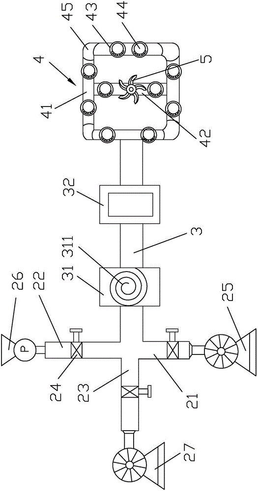
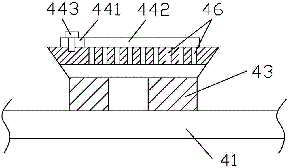
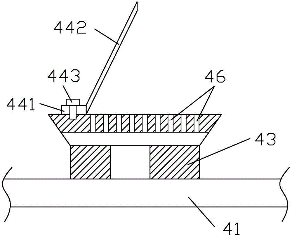
[0045] Such as Figure 1-7 As shown, it is a landscape river aeration device of the present invention, including a mounting frame 1, an air intake device, a main pipe 3, an aeration pipe 4 and a rotating impeller 5, and the main pipe 3 is connected with a gas-liquid mixer 31 and air bubbles Generator 32, the air intake device is connected to the gas-liquid mixer 31, the bubble generator 32 is respectively connected to the gas-liquid mixer 31 and the aeration pipe 4, and the air intake device includes an air intake pipe 21, a high-pressure water inlet pipe 22 and an oxygen intake pipe 23. The air inlet pipe 21, the high-pressure water inlet pipe 22 and the oxygen inlet pipe 23 are respectively connected to the main pipe 3, and the high-pressure air is passed into the air inlet pipe 21, and the high-pressure water is passed into the high-pressure water inlet pipe 22, and the oxygen inlet pipe 23 Oxygen or ozone is passed into the middle, and it is initially mixed at the intersec...


PUM


Abstract

The invention mainly discloses a landscape river aeration device and aeration method. The technical scheme is as follows: the device comprises a mounting rack, a gas inlet unit, a main pipeline, an aeration pipe and a rotary impeller, wherein the main pipeline is connected with a gas-liquid mixture and a bubble generator; the gas inlet unit comprises an air inlet pipe, a high-pressure water inlet pipe and an oxygen gas inlet pipe; the aeration pipe is composed of four aeration branch pipes which communicate with each other end to end; a connecting pipe is arranged between the two aeration branch pipes which are symmetrically arranged; the rotary impeller is installed on the connecting pipe; and the aeration branch pipes and connecting pipes are respectively provided with a sprayer on which a diaphragm is covered. The method comprises bubble aeration and surface aeration, has the advantages of simple installation, stable structure, favorable firmness and reasonable design, and is beneficial to implementing large-scale high oxygen solubility of the water body and enhancing the oxygen dissolution efficiency. By arranging the diaphragms, the aeration pores can not be easily blocked, thereby prolonging the service life of the aeration pipe, reducing the cleaning frequency and lowering the maintenance cost.

Description

technical field [0001] The invention relates to a landscape river aeration device and an aeration method. Background technique [0002] In recent years, as the pollution of rivers and lakes has become more and more serious, people have gradually shifted from a single urban sewage treatment to a large concept of river and lake treatment. There are various treatment methods for rivers and lakes, but the most effective method is the combination of biochemical and ecological treatment. One of the biggest problems to be solved in biochemical treatment is aeration in the river. The principle of aeration is to fully contact water and air to exchange gaseous substances and remove volatile substances in water, or to make gas escape from water, such as removing water Odor or harmful substances such as titanium dioxide and hydrogen sulfide, or oxygen into the water to increase the concentration of dissolved oxygen, to remove iron, manganese or promote aerobic microorganisms to degrade...

Claims


Application Information

Patent Timeline
IPC IPC(8): C02F7/00C02F3/02C02F3/32C02F3/34
CPCC02F3/02C02F3/327C02F3/34C02F7/00Y02W10/10
Inventor 陈宏刚周勇明陈庆锋张龙周静霞
Owner 杭州市城市土地发展有限公司
Learn More