Rotating disc type automatic quenching device

A quenching device and turntable technology, which is applied in the direction of quenching devices, energy efficiency improvement, heat treatment equipment, etc., can solve the problems of difficult control of metal workpieces, low yield of metal quenching treatment, difficulty in ensuring hardened layer, etc., and achieve rotation angle control Precise, smooth turntable rotation, smooth sliding effect

Active Publication Date: 2016-10-26
邯郸市翔天数控工程有限公司
View PDF5 Cites 18 Cited by
  • Summary
  • Abstract
  • Description
  • Claims
  • Application Information

AI Technical Summary

Problems solved by technology

[0002] At present, the domestic industry generally adopts manual high-frequency quenching, or non-professional semi-automatic numerical control high-frequency quenching, which mainly uses manual induction heating and quenching of metal workpieces one by one on the quenching machine, or quickly Immersed in a water pool (oil pool) for cooling, due to manual operation, it is impossib...

Method used


Image

  • Rotating disc type automatic quenching device
  • Rotating disc type automatic quenching device
  • Rotating disc type automatic quenching device

Examples


Embodiment Construction

[0034] Below in conjunction with embodiment the present invention is described in further detail:

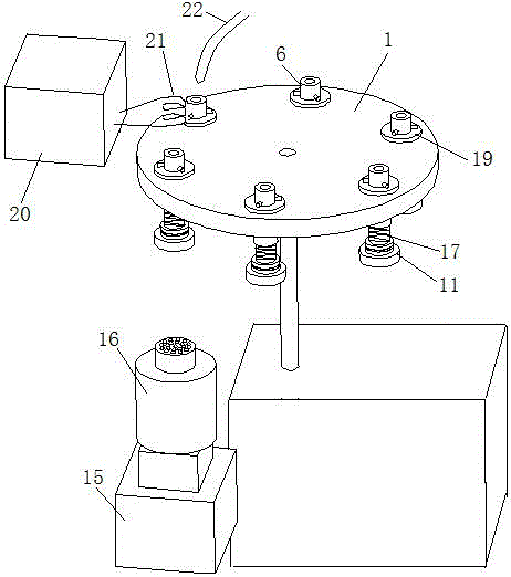
[0035] Such as figure 1As shown, the turntable type automatic quenching device includes a horizontal turntable 1 driven by a driving device. At least 3 slideways are evenly distributed around the central axis of the turntable 1 on the turntable 1. A sliding sleeve 19 is fixed inside the slideway. Inside the slide sleeve 19 There is a pusher rod 6 that slides up and down along the slideway. The center of the pusher rod 6 is provided with a positioning groove 7 for fixing the quenching parts. Some of the quenching parts are of spherical structure, and the quenching parts of the spherical structure are placed on the pusher of the plane. It is difficult to realize positioning on the rod, and the positioning groove 7 better solves the problem of difficult positioning of spherical quenched parts. A quenching induction coil 21 and a cooling nozzle 22 are sequentially arranged above th...


PUM


Abstract

The invention discloses a rotating disc type automatic quenching device, and belongs to the technical field of heat treatment equipment. The rotating disc type automatic quenching device comprises a rotating disc. The rotating disc is driven by a driving device and is horizontally arranged. At least three slipways are uniformly distributed on the rotating disc and around the central axis of the rotating disc. Pushing rods capable of sliding up and down along the slipways are arranged in the slipways. A quenching induction coil and a cooling pipe orifice are sequentially arranged on the rotating disc in the rotating direction of the rotating disc, are arranged on the movement loci of the pushing rods and are respectively opposite to the two adjacent pushing rods. A motor, driven by a pneumatic cylinder II to move up and down, is arranged below the rotating disc and at a corresponding position of the quenching induction coil. A quick connecting device for transmitting torque is arranged at the upper end of an output shaft of the motor and the lower ends of the pushing rods. Heating, cooling and taking and placing of parts are conducted synchronously and do not affect one another, the quenching efficiency is improved greatly, and besides, quenching parts uninterruptedly rotate at constant speed in the quenching induction coil along with the pushing rods, and are guaranteed to be heated more uniformly.

Description

technical field [0001] The invention relates to a quenching device, in particular to an automatic quenching device, which belongs to the field of heat treatment equipment. Background technique [0002] At present, the domestic industry generally adopts manual high-frequency quenching, or non-professional semi-automatic numerical control high-frequency quenching, which mainly uses manual induction heating and quenching of metal workpieces one by one on the quenching machine, or quickly Immersed in a water pool (oil pool) for cooling, due to manual operation, it is impossible to control the continuity of rapid heating of metal workpieces, it is difficult to control the size of the quenching hardness transition zone of metal workpieces, and it is also difficult to ensure the internal distribution of the hardened layer and the high frequency The uniformity of quenching hardness results in low yield and poor effect of metal quenching treatment. Contents of the invention [000...

Claims


Application Information

Patent Timeline
IPC IPC(8): C21D1/667C21D1/42
CPCC21D1/42C21D1/667Y02P10/25
Inventor 李慧英
Owner 邯郸市翔天数控工程有限公司
Why Eureka
Try Eureka