A timing chain transmission mechanism

A technology of transmission mechanism and timing chain, which is applied in the direction of transmission, engine components, machines/engines, etc., can solve the problems of reducing strength requirements, achieve the effects of reducing strength requirements, avoiding swing, and reducing internal wear

Active Publication Date: 2018-09-18
GUANGZHOU AUTOMOBILE GROUP CO LTD
View PDF5 Cites 0 Cited by
  • Summary
  • Abstract
  • Description
  • Claims
  • Application Information

AI Technical Summary

Problems solved by technology

[0005] The purpose of the present invention is to provide a timing chain transmission mechanism, which can solve the existing problems of the existing timing chain transmission mechanism, effectively reduce the strength requirements of the chain in the timing chain transmission mechanism, and reduce the internal wear of the chain and the engine noise

Method used


Image

  • A timing chain transmission mechanism
  • A timing chain transmission mechanism
  • A timing chain transmission mechanism

Examples


Embodiment Construction

[0022] The following will clearly and completely describe the technical solutions in the embodiments of the present invention with reference to the accompanying drawings in the embodiments of the present invention. Obviously, the described embodiments are only some, not all, embodiments of the present invention. Based on the embodiments of the present invention, all other embodiments obtained by persons of ordinary skill in the art without creative efforts fall within the protection scope of the present invention.

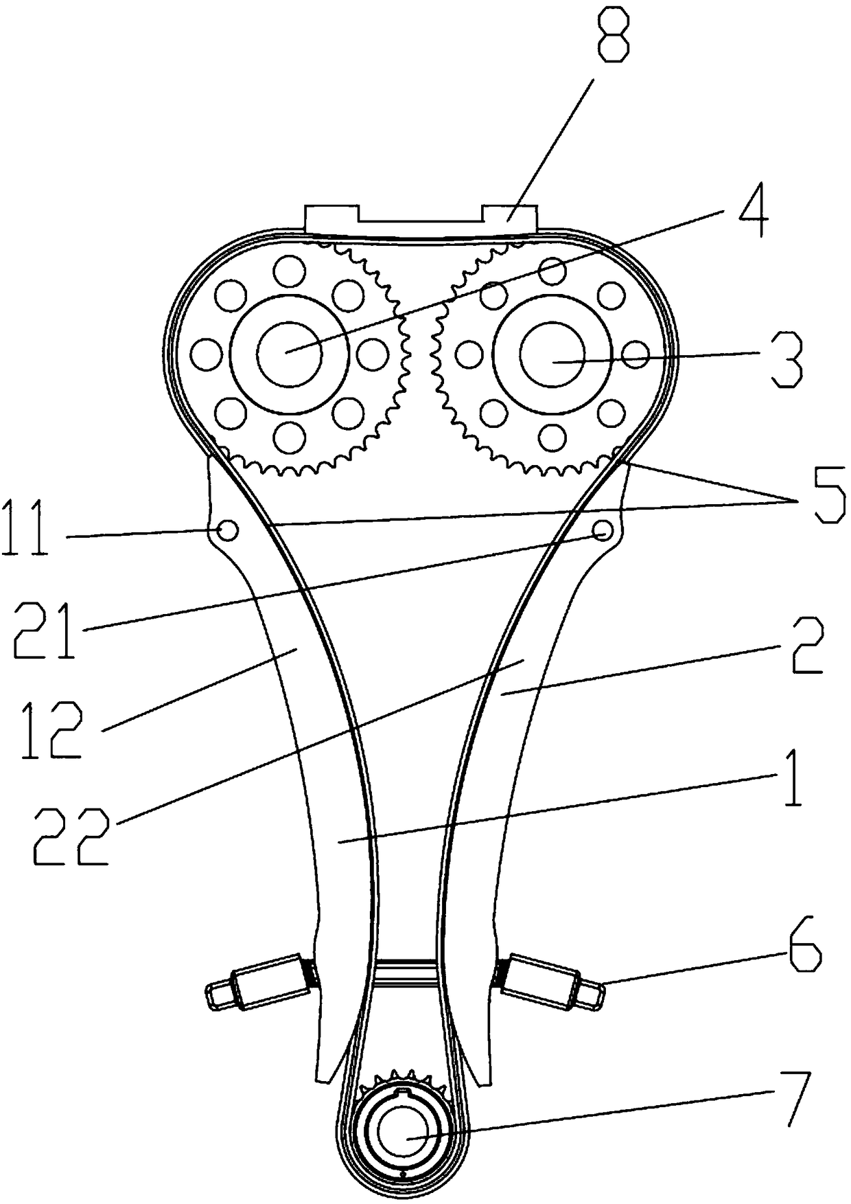
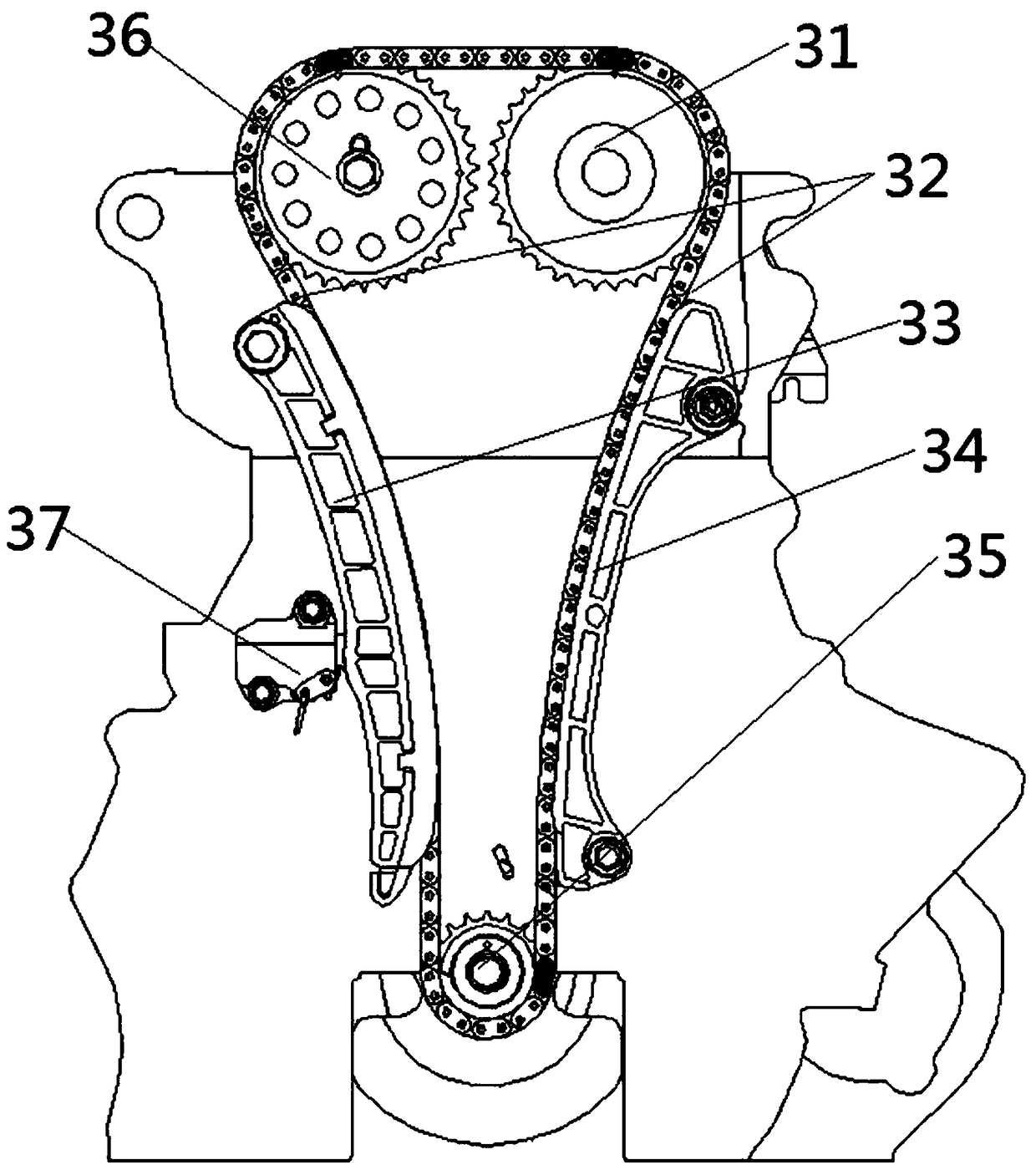
[0023] see Figure 1 to Figure 2 As shown, the present invention provides a timing chain transmission mechanism, which includes a crankshaft sprocket 7, an intake camshaft sprocket 3, an exhaust camshaft sprocket 4 and surrounding the crankshaft sprocket 7, the intake camshaft The gas camshaft sprocket 3 and the chain of the exhaust camshaft sprocket 4, the timing chain transmission mechanism also includes a first moving guide rail 1, a second moving guide rail 2 a...


PUM


Abstract

The invention provides a timing chain transmission mechanism. The timing chain transmission mechanism comprises a crankshaft sprocket, a gas inlet cam shaft chain wheel, an exhaust cam shaft chain wheel and a chain surrounding the crankshaft sprocket, the gas inlet cam shaft chain wheel and the exhaust cam shaft chain wheel. The timing chain transmission mechanism further comprises a first movable guide rail, a second movable guide rail and a two-way tensioner. The first movable guide rail and the second movable guide rail are oppositely arranged on the outer side of the chain. The two-way tensioner is clamped on the outer side of the first movable guide rail and the outer side of the second movable guide rail. The timing chain transmission mechanism has the beneficial effects that by means of cooperation of the first movable guide rail, the second movable guide rail and the two-way tensioner, the requirement for the strength of the chain in the timing chain transmission mechanism is lowered, and the internal abrasion of the chain is reduced; and meanwhile, because the chain is kept at the appropriate tightness degree all the time in the work operation process of the timing chain transmission mechanism, the problem that because the chain is too loose, the chain swings is solved, and vibration and noise of engines are reduced.

Description

technical field [0001] The invention relates to the field of motor vehicles, in particular to a timing chain transmission mechanism. Background technique [0002] During the working process of the engine of a motor vehicle, the four processes of intake air, compression, work, and exhaust continuously occur in the cylinder, and the timing of each step must match the movement state and position of the piston, so that the air intake and exhaust and the piston lifting are coordinated with each other, through the timing transmission system, the power is transmitted to the camshaft under the drive of the crankshaft, so that the intake and exhaust valves of the engine are opened or closed at an appropriate time, ensuring that the engine cylinder can normally inhale and exhaust . [0003] In the prior art, most of the timing drive system of the engine adopts chain drive, such as image 3 as shown, image 3 A conventional engine timing chain drive is shown. This mechanism comprises...

Claims


Application Information

Patent Timeline
Patent Type & Authority Patents(China)
IPC IPC(8): F16H7/06F16H7/08F01L1/348
CPCF01L1/348F16H7/06F16H7/08
Inventor 周许英花力纯陈良占文锋刘巨江邵发科
Owner GUANGZHOU AUTOMOBILE GROUP CO LTD
Why Eureka
Try Eureka