
Test method for simulating combined load effect of explosive shock waves and high-speed fragment groups

A technology of combined load and test method, which is applied to the measurement of blasting force, ammunition test, offensive equipment, etc., can solve the problems of long design and production cycle, high grid density, and low test cost

Inactive Publication Date: 2016-10-26
NAVAL UNIV OF ENG PLA
View PDF3 Cites 17 Cited by
  • Summary
  • Abstract
  • Description
  • Claims
  • Application Information

AI Technical Summary

Problems solved by technology

In the design of protective structures, the joint damage effect of these two loads must be considered, and it is far from enough to only consider the damage effect of a single load
[0003] At present, the research on the joint damage effect of the weapon warhead on the target structure is mainly realized through the following three methods: (1) live ammunition explosion test; this method can obtain real, accurate and reliable damage results, but the model size is large and the design and production cycle is long , high manufacturing cost, high cost, and difficult to implement; (2) Numerical simulation; this method is subject to two conditions, one is that the calculation of the explosion field requires a large grid density, a large number of elements, and a long calculation time, so the calculation cost is very high Second, there are multiple coupling effects of gas and solids in the explosion field, and the existing algorithms are difficult to accurately simulate this situation, and the accuracy cannot be guaranteed, and numerical simulation requires a large number of experiments to provide basic data and correction basis; (3) simulation experiments ; This method is to carry out the warhead damage effect test by establishing an equivalent model of the defense target and target structure; the test cost of this method is lower than that of the live ammunition explosion test, and the test effect is basically equivalent to the live ammunition explosion test under a suitable scale. It is a very effective method used in current research; however, this method has very strict requirements on the conditions of the test site. In order to ensure the safety of personnel and test equipment, the test must be carried out in a large open and hidden test site (requiring a lot of manpower and material resources to carry out the test) safety inspection of the test site), or strict auxiliary protective facilities must be installed around the test model; if the scale of the model is too large, the test site is required to be more concealed, or the auxiliary protective facilities are thicker, which requires more requirements for the test site conditions. For the harsh, need to spend more manpower and material resources

Method used


Image

  • Test method for simulating combined load effect of explosive shock waves and high-speed fragment groups
  • Test method for simulating combined load effect of explosive shock waves and high-speed fragment groups
  • Test method for simulating combined load effect of explosive shock waves and high-speed fragment groups

Examples


Embodiment 1

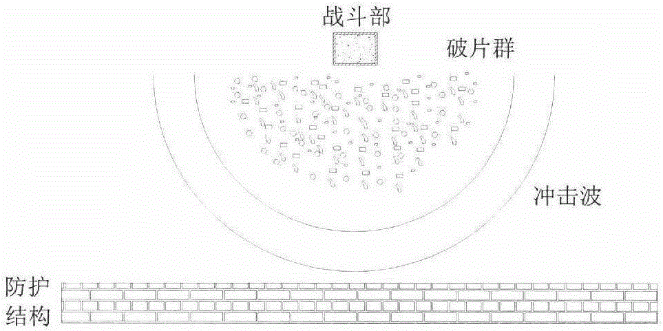
[0081] Embodiment 1. This example is a test method for simulating the combined load of the explosion shock wave and the high-speed fragment group that a certain cylindrical warhead explodes in the air, such as figure 2 As shown, it is a schematic diagram of the fragments flying after the explosion of the warhead;

[0082] Include the following steps:

[0083] (1) Determine the distribution steps of equivalent prefabricated fragments, including the following sub-steps:

[0084] (1.1) Determine the scale warhead model size;

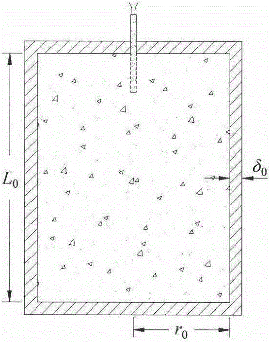
[0085] The defense target warhead is cylindrical, the charge is TNT charge, and the charge density is 1610kg / m 3 , the charge length is 0.50m, and the charge radius is 0.175m; the warhead shell material is 45# steel, and the shell thickness is 0.02m;

[0086] According to the requirements of similar theory and test conditions, the scale ratio of the scaled model is determined to be 1:5, that is, the scaled warhead is still cylindrical, and the charge is...

Embodiment 2

[0114] Embodiment two, this example is the test method for simulating the explosion shock wave and high-speed fragment joint load that certain spherical warhead air explosion produces, as figure 2 As shown, it is a schematic diagram of the fragments flying after the explosion of the warhead;

[0115] Include the following steps:

[0116] (1) Determine the distribution steps of equivalent prefabricated fragments, including the following sub-steps:

[0117] (1.1) Determine the scale warhead model size;

[0118] The defense target warhead is spherical, the charge is Octo gold charge, and the charge density is 1890kg / m 3 , the charge radius is 0.2m; the warhead shell material is 30CrMnSiNi2A, and the shell thickness is 0.02m;

[0119] According to the requirements of similar theory and test conditions, the scale ratio of the scaled model is determined to be 1:4, that is, the scaled warhead is still spherical, and the charge is made of octogold. The profile of the spherical war...


PUM

PropertyMeasurementUnit
densityaaaaaaaaaa
thicknessaaaaaaaaaa
densityaaaaaaaaaa

Abstract

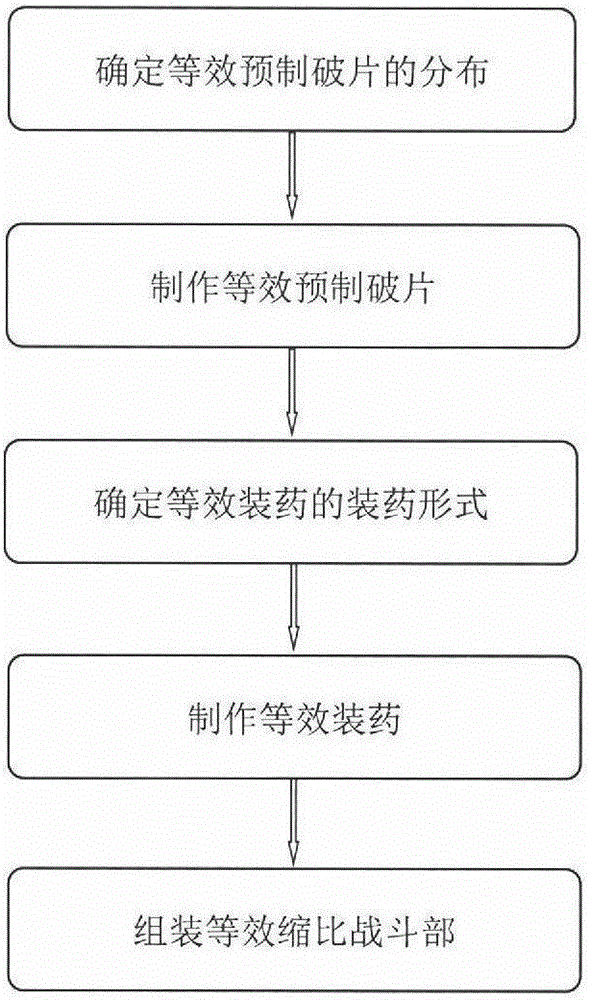
The invention relates to a test method for simulating the combined load effect of explosive shock waves and high-speed fragment groups formed after close-range explosion of a weapon warhead. The test method includes the five steps of 1, determining the size of a scaled-down warhead model, calculating the initial speed of fragments, the number of the target-reaching fragments of target structures and the mass distribution of the fragments after explosion occurs, and calculating the mass, the size and the number of equivalent preformed fragments; 2, manufacturing the equivalent preformed fragments in the step 1; 3, determining the propellant types of equivalent propellants such as the propellant kind, the propellant shape and the propellant size; 4, manufacturing the equivalent propellants in the step 3; and 5, assembling the equivalent preformed fragments in the step 2, the equivalent propellants in the step 4 and detonating electric detonators for forming an equivalent scaled-down warhead.

Description

technical field [0001] The invention relates to the field of protection engineering, in particular to a test method that can be used to simulate the joint damage and damage effect of the explosion shock wave formed after the close-range explosion of the weapon warhead and the high-speed dense fragment group on the protection structure, personnel equipment, etc. Background technique [0002] With the rapid development of weapon technology, the performance of modern weapons has been greatly enhanced. When the charge of the warhead is detonated and the shell is broken, two kinds of damage loads, blast shock wave and high-speed fragments, will be formed. Explosion shock waves and high-speed fragments are the main factors that cause damage to protective structures caused by the explosion of conventional ammunition. The fragment damage load belongs to the local strong impact load, and its impact energy density is very high. Through the high-speed impact and penetration of the fra...

Claims


Application Information

Patent Timeline
Patent Type & Authority Applications(China)
IPC IPC(8): F42B35/00G01L5/14G01N3/313
CPCF42B35/00G01L5/14G01N3/313
Inventor 侯海量李茂李典朱锡陈长海
Owner NAVAL UNIV OF ENG PLA
Learn More