
A Calibration Method of Electric Wave Refraction Correction Effect Using Precise Ballistic

A technology of radio wave refraction and calibration method, applied in satellite radio beacon positioning systems, radio wave measurement systems, instruments, etc., can solve the problem that the evaluation accuracy is limited by the observation period and geographical location, cannot reflect the direction of radio wave propagation, and laser ranging The impact of data is relatively large, and the evaluation process is concise and clear, avoiding the impact of oscillation, and achieving the effect of strong objectivity.

Active Publication Date: 2018-12-11
CHINA XIAN SATELLITE CONTROL CENT
View PDF5 Cites 0 Cited by
  • Summary
  • Abstract
  • Description
  • Claims
  • Application Information

AI Technical Summary

Problems solved by technology

In the practical application of spacecraft atmospheric refraction inspection and evaluation, these methods need to add corresponding standard observation equipment for evaluation at each station, and the detection time is limited, so evaluation cannot be continuously provided. The evaluation accuracy is affected by the observation period and geographical location. limit
Obtaining the atmospheric refraction profile is limited by the assumption error of the model formula, the conversion error of the refractive index formula, the error of the atmospheric structure measurement method, the position of the station, and the observation time. The sounding balloon and the vertical survey instrument can only obtain the atmospheric refraction in the vertical direction above the station Rate profile, atmospheric refractive index profile that cannot reflect the direction of radio wave propagation, microwave radiometer and dual-frequency method are affected by the accuracy of detection equipment and abnormal data fluctuations; laser ranging data requires cooperative targets and is greatly affected by weather factors

Method used


Image

  • A Calibration Method of Electric Wave Refraction Correction Effect Using Precise Ballistic
  • A Calibration Method of Electric Wave Refraction Correction Effect Using Precise Ballistic
  • A Calibration Method of Electric Wave Refraction Correction Effect Using Precise Ballistic

Examples


Embodiment Construction

[0024] The present invention will be further described below in conjunction with the accompanying drawings and embodiments, and the present invention includes but not limited to the following embodiments.

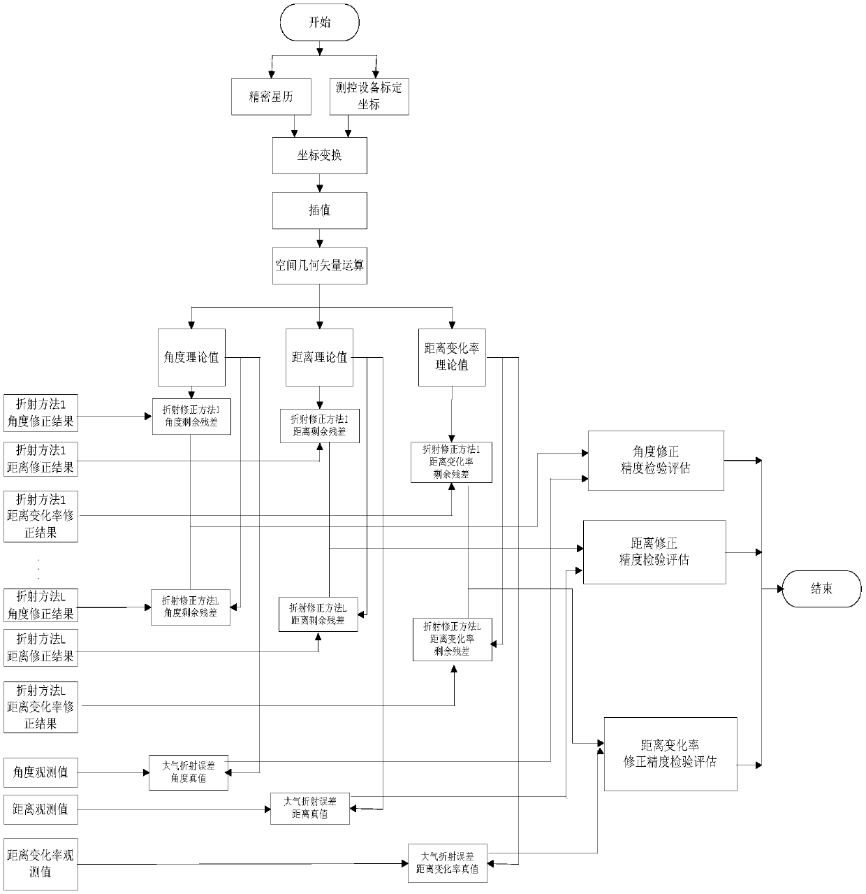
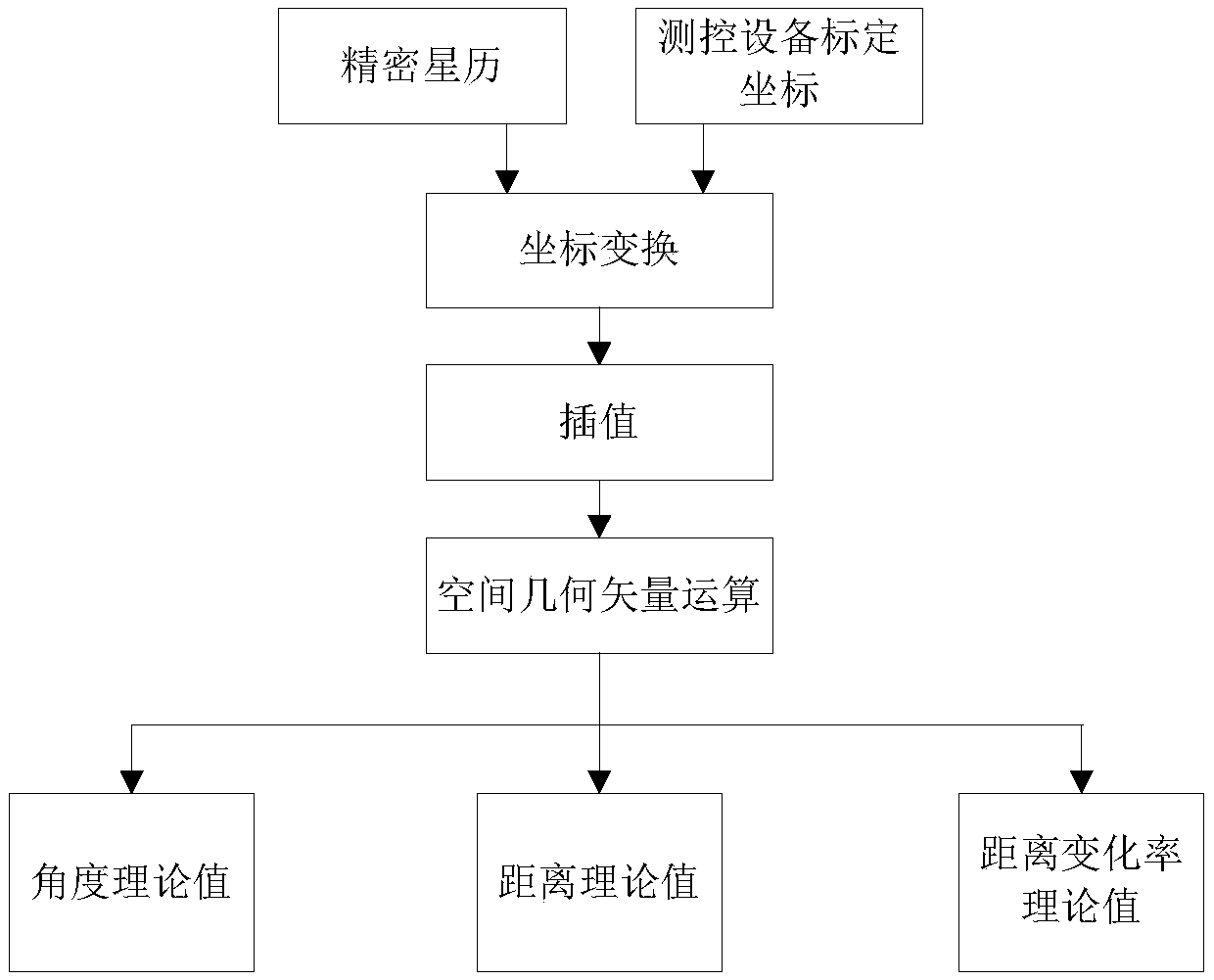
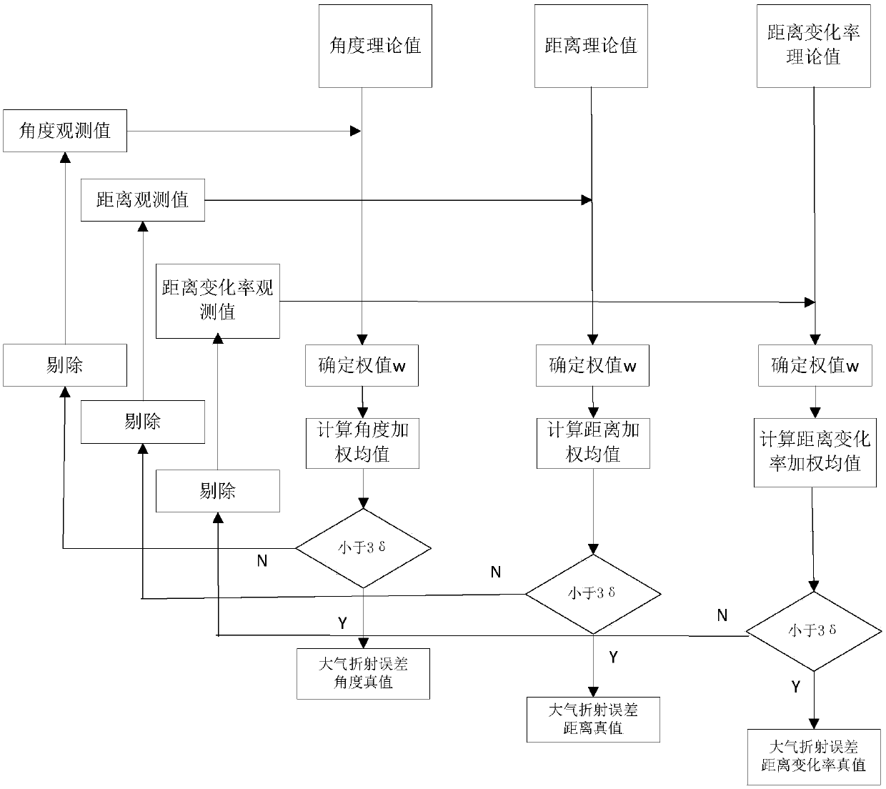
[0025] The invention utilizes laser distance measurement or space-borne GPS distance measurement or altimeter data to obtain the precise ballistic trajectory of the satellite, and the calibration coordinates of the geometric center of the measurement and control equipment obtained by geodesy. Through precise ephemeris and measurement and control equipment coordinate conversion, and space geometry vector calculation, the standard values ​​of the external measurement elements are obtained, and the main errors and residual errors caused by atmospheric refraction are solved based on the external measurement data observation values ​​and the standard values ​​of each measurement element. , designed a test model for quantitatively evaluating the effect of atmospheric refraction co...


PUM


Abstract

The invention provides a method for calibrating radio wave refraction correction effects by virtue of a precision trajectory. A precision trajectory of a satellite is obtained by virtue of laser ranging or satellite-born GPS ranging or altimeter data, a calibrated coordinate of a geometric center of measurement and control equipment is acquired by geodetic measurement, a standard value of each measurement element for exterior measurement is obtained by precise ephemeris and measurement and control equipment coordinate conversion as well as spatial geometric vector calculation, a main error and post-fit residual caused by atmospheric refraction are solved according to an observed value of exterior measurement data and the standard value of each measurement element, a testing model for quantitatively evaluating atmospheric refraction correction effects is designed, and the refraction correction accuracy is calculated. According to the method, time and space limits are broken, and the refraction correction effects of each measurement element for exterior measurement can be tested and evaluated in real time.

Description

technical field [0001] The invention relates to the field of on-orbit spacecraft measurement and control management, and is suitable for the inspection and evaluation of the atmospheric refraction correction effect of spacecraft external measurement data. Background technique [0002] Atmospheric refraction brings errors to the measurement data of the aerospace external measurement system and satellite navigation system. To improve the positioning and measurement accuracy of the spacecraft, it is necessary to correct the measured apparent distance, angle and speed of the radio wave refraction to compensate for the space environment. measurement error. Compensating the measurement error caused by atmospheric refraction is one of the tasks in the data processing of spacecraft external ballistic measurement. Atmospheric refraction correction methods currently used can be classified as corrections with models or measured atmospheric refractivity profiles and propagation correct...

Claims


Application Information

Patent Timeline
Patent Type & Authority Patents(China)
IPC IPC(8): G01C25/00G01S19/40
CPCG01C25/00G01S19/40
Inventor 赵军王西京陈建荣洪涛张莹陈学军赵鞭张华张冲难浦仕保
Owner CHINA XIAN SATELLITE CONTROL CENT
Learn More