Cavity impedance band elimination filter

A band-stop filter and cavity technology, applied in waveguide devices, electrical components, circuits, etc., can solve problems such as poor frequency stability, mode hopping, and large volume, and achieve the goal of improving power level and spectral purity performance Effect

Inactive Publication Date: 2016-10-26
CHENGDU ZHONGWEI ELECTRONICS MICROWAVE TECH
View PDF0 Cites 0 Cited by
  • Summary
  • Abstract
  • Description
  • Claims
  • Application Information

AI Technical Summary

Problems solved by technology

[0006] Different from the situation of the prior art, the beneficial effect of the present invention is: by adopting the resonator, it overcomes the problems of large volume, small output power, poor frequency stability and limited Changes in external conditions (such as load, temperature, voltage, etc.) may cause defects such as unstable phenomena such as mode hopping, thereby improving the power level and spectral purity of the output microwave signal

Method used


Image

  • Cavity impedance band elimination filter
  • Cavity impedance band elimination filter

Examples


Embodiment Construction

[0009] The following will clearly and completely describe the technical solutions in the embodiments of the present invention with reference to the accompanying drawings in the embodiments of the present invention. Obviously, the described embodiments are only some, not all, embodiments of the present invention. Based on the embodiments of the present invention, all other embodiments obtained by persons of ordinary skill in the art without making creative efforts belong to the protection scope of the present invention.

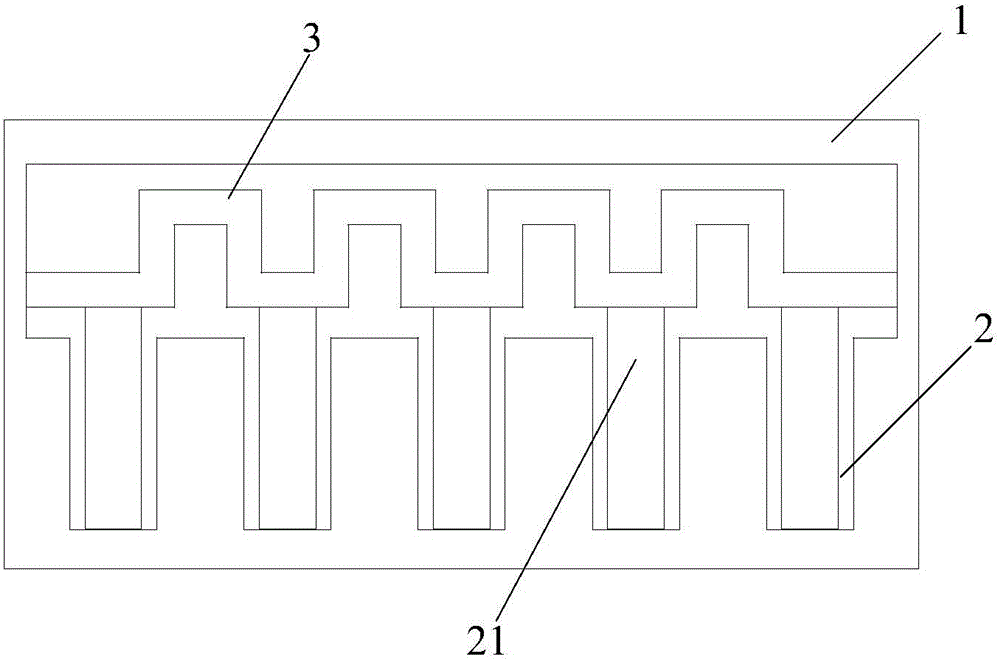
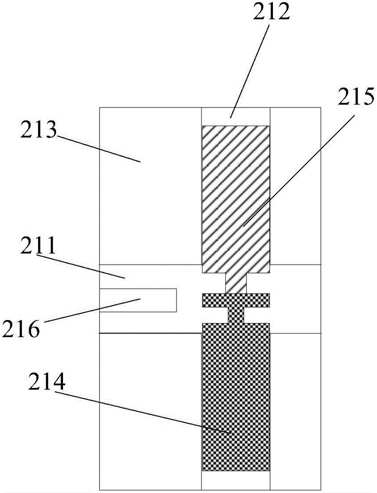
[0010] see also Figure 1 to Figure 2 , the cavity impedance band-stop filter of the embodiment of the present invention includes a cavity 1, a plurality of resonant cavities 2 arranged in sequence are arranged in the cavity 1, a resonator 21 is arranged in the resonant cavity 2, and the resonator 21 is composed of an oscillating cavity 211 , a conversion cavity 212, a tube base 213, a feed terminal 214, a body effect diode 215, and a dielectric resonator rod ...


PUM


Abstract

A cavity impedance band elimination filter provided by the present invention comprises a cavity in which a plurality of orderly arranged resonant cavities are arranged, resonators are arranged in the resonant cavities, and each resonator is composed of an oscillation cavity, a conversion cavity, a tube socket, a feed terminal, a bulk effect diode and a dielectric resonance rod. The oscillation cavity is arranged in the radial direction of the tube socket, the conversion cavity is arranged in the axial direction of the tube socket, and the bulk effect diode is arranged at one end of the conversion cavity. The feed terminal is arranged at the other end of the conversion cavity, the dielectric resonance rod is fixed in the oscillation cavity, and transmission lines in a rectangular wave shape are also arranged in the cavity and are connected with the ends of the resonators far away from the feed terminals. By the above mode, and according to the present invention, a power level of outputting a microwave signal and a frequency spectrum purity performance can be improved.

Description

technical field [0001] The invention relates to the technical field of microwave communication, in particular to a cavity impedance band-stop filter. Background technique [0002] Cavity impedance bandstop filter is a key device in microwave communication system. In practical applications, it is often necessary to take appropriate frequency stabilization measures to improve its frequency stability. Among them, high-Q frequency stabilization cavity, injection locking, and phase-locked loop frequency stabilization are three commonly used methods. The widely used frequency stabilization technology is to add a high-Q frequency stabilization cavity to increase the total energy storage of the oscillation circuit, thereby improving the frequency stability of the oscillator. [0003] However, the traditional cavity impedance band-stop filter mostly adopts a reflective high-Q cavity frequency stabilization method, the output power is small, and the frequency stability is generally o...

Claims


Application Information

Patent Timeline
Patent Type & Authority Applications(China)
IPC IPC(8): H01P1/208
CPCH01P1/208
Inventor 蒋孝林李翔
Owner CHENGDU ZHONGWEI ELECTRONICS MICROWAVE TECH
Why Eureka
Try Eureka