
Method for estimating rotor position of three-stage brushless AC synchronous motor

A technology of AC synchronous motor and rotor position, which is applied in the direction of synchronous generator control, control generator, motor generator control, etc. It can solve problems such as fault failure, zero position error, and decreased accuracy of position sensor, so as to reduce weight, The effect of reducing complexity

Active Publication Date: 2016-10-26
NANJING UNIV OF AERONAUTICS & ASTRONAUTICS
View PDF2 Cites 27 Cited by
  • Summary
  • Abstract
  • Description
  • Claims
  • Application Information

AI Technical Summary

Problems solved by technology

However, under aviation conditions, unfavorable conditions such as aircraft vibration, high temperature, low temperature, and electromagnetic interference may reduce the accuracy of the position sensor, or even malfunction.
Using a resolver as a position sensor to obtain position information has good stability, but due to the installation process of the resolver, there may be a zero position error, which makes it impossible to obtain accurate rotor position information when the motor is started.

Method used


Image

  • Method for estimating rotor position of three-stage brushless AC synchronous motor
  • Method for estimating rotor position of three-stage brushless AC synchronous motor
  • Method for estimating rotor position of three-stage brushless AC synchronous motor

Examples


Embodiment Construction

[0038] The technical solutions of the present invention will be described in detail below in conjunction with the accompanying drawings.

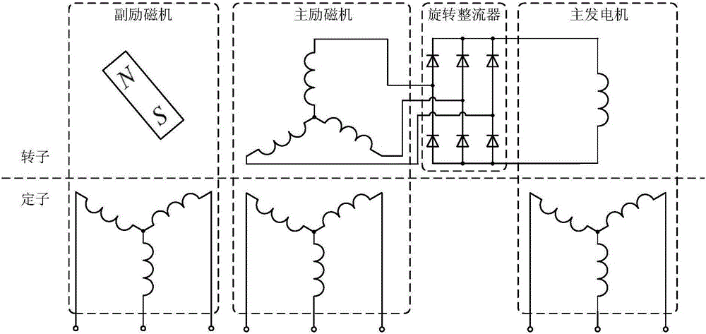
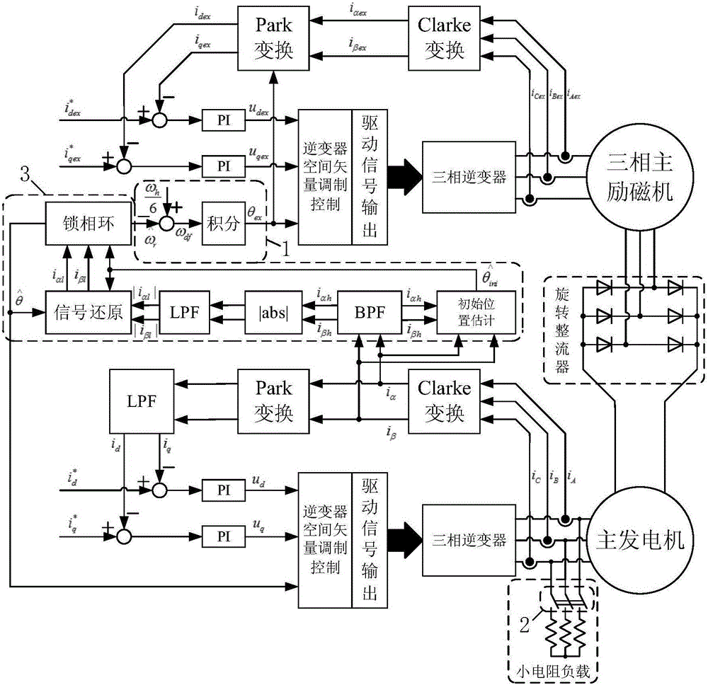
[0039] figure 1 Shown is a schematic structural diagram of a three-stage brushless AC synchronous motor applicable to the present invention, wherein the main generator is connected to the main exciter through a rotating rectifier, and the main exciter is a three-phase excitation winding, where the three-phase excitation winding is connected to Input a certain frequency of three-phase alternating current, the three-phase alternating current is used as the three-phase excitation current of the main exciter, set the slip frequency between the excitation magnetic potential and the motor rotor as one-sixth of the frequency of the high-frequency signal to be injected, and the rotor side The induced alternating current generates direct current with high-frequency harmonic components after passing through the rotating rectifier, which provides exci...


PUM


Abstract

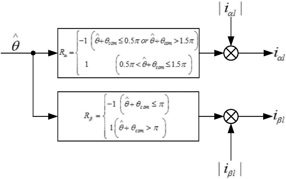
The invention discloses a method for estimating a rotor position of a three-stage brushless AC synchronous motor. A main exciter of the three-stage brushless AC synchronous motor is a three-phase field winding, and a three-phase alternating current is connected to the three-phase field winding, wherein the three-phase alternating current acts as the three-phase exciting current of the main exciter; the slip frequency of exciting magnetic potential and motor rotors is set as one-sixth of the high-frequency signal frequency that is expected to be injected; and after the alternating current induced at the rotor side passes a rotary rectifier, a DC current with high-frequency harmonic components is generated so as to provide excitation for the main generator field winding, detect output current of the main generator, and realize the determination of the initial motor rotor position and the estimation of the rotor position during the starting operation. By use of the method for estimating the position disclosed by the present invention, a more accurate position estimation value can be obtained, and the method is insensitive to the accuracy of the injected high-frequency signal frequency and phase, and has certain anti-interference ability.

Description

technical field [0001] The invention belongs to the technical field of motor control, in particular to a method for estimating the rotor position of a three-stage brushless synchronous motor. Background technique [0002] In recent years, multi-electric aircraft and all-electric aircraft have become the main development direction of large aircraft technology, and three-stage brushless synchronous motors have been widely used as generators in aviation AC power systems. Using a three-stage brushless synchronous motor to start under electric state can save special starting equipment, reduce the weight of airborne equipment, reduce flight costs, reduce the scale of the starting power generation system, and reduce the complexity of the system. For example, Boeing's B787 passenger plane uses four three-stage brushless synchronous motors with integrated starter and power generation. [0003] The frequency conversion AC power system is a key development direction of the civil aviat...

Claims


Application Information

Patent Timeline
IPC IPC(8): H02P21/18H02P21/34H02P103/20H02P101/30
CPCH02P2101/30H02P2103/20
Inventor 杨袁钰魏佳丹姜宇周波王晓波薛嘉成
Owner NANJING UNIV OF AERONAUTICS & ASTRONAUTICS
Learn More