Flue gas waste heat recovery device with vertical low-resistance heat pipes

A technology of a flue gas waste heat and recovery device, which is applied in the field of flue gas waste heat recovery, can solve the problems of blockage of the gas outlet, low exchange efficiency, environmental heat pollution, etc., and achieves improved heat exchange efficiency, increased heat transfer effect, and low heat exchange coefficient. Effect

Inactive Publication Date: 2016-11-02
SUZHOU BSE AIR CONDITIONER
View PDF8 Cites 0 Cited by
  • Summary
  • Abstract
  • Description
  • Claims
  • Application Information

AI Technical Summary

Problems solved by technology

[0002] In many industrial productions, a large amount of high-temperature exhaust gas is discharged, and these exhaust gases are usually discharged directly, which not only causes waste of heat energy, but also produces thermal pollution to the environment
Although there are many waste heat recovery and utilization devices at present, the exchange efficiency of the heat exchangers currently used is low, and there is still a large amount of waste of heat energy.
Moreover, when these devices recover waste heat from dusty flue gas, it will cause the problem of blockage of the air outlet.

Method used


Image

  • Flue gas waste heat recovery device with vertical low-resistance heat pipes
  • Flue gas waste heat recovery device with vertical low-resistance heat pipes
  • Flue gas waste heat recovery device with vertical low-resistance heat pipes

Examples


Embodiment Construction

[0019] The present invention will be described in further detail below in conjunction with the accompanying drawings.

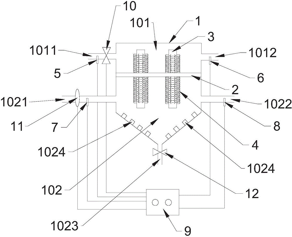
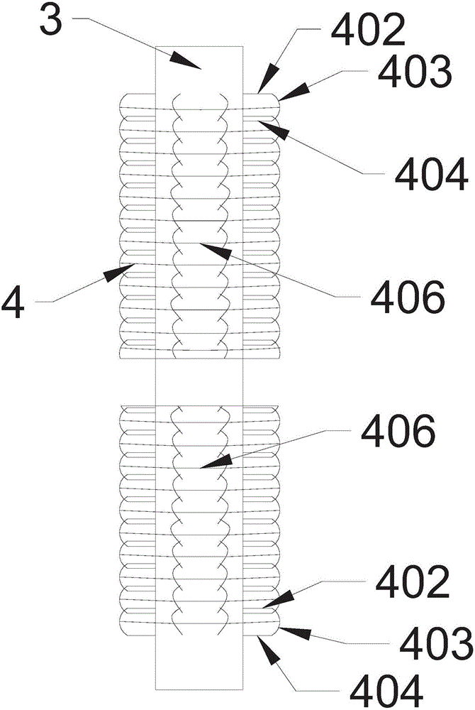
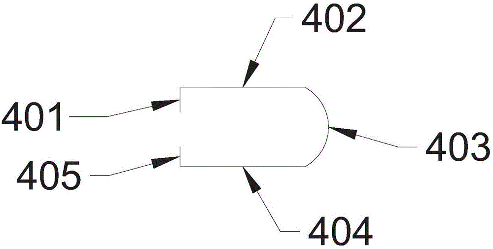
[0020] Figure 1 to Figure 4 Schematically shows a flue gas waste heat recovery device with vertical low-resistance heat pipes according to an embodiment of the present invention. As shown in the figure, the flue gas waste heat recovery device with vertical low-resistance heat pipes includes a shell 1, a heat shield 2 and several heat pipes 3, and the material of the heat shield 2 can be selected by technicians according to actual needs; the shell 1. The upper shell 101 and the lower shell 102 are separated by the heat insulation plate 2. The heat exchange medium inlet 1011 and the heat exchange medium outlet 1012 are respectively provided on both sides of the upper shell 101. The heat exchange medium is used to store the flue gas from The heat recovered in the heat exchange medium can be water or other fluids. The two sides of the lower housing 102 are resp...


PUM


Abstract

The invention discloses a flue gas waste heat recovery device with vertical low-resistance heat pipes. The flue gas waste heat recovery device with the vertical low-resistance heat pipes comprises a shell body, a thermal insulation plate and a plurality of heat pipes. The inner cavity of the shell body is separated into an upper shell body and a lower shell body by the thermal insulation plate. A heat exchanging medium inlet and a heat exchanging medium outlet are arranged at two sides of the upper shell body separately and a flue gas inlet and a flue gas outlet are arranged at two sides of the lower shell body separately. The plurality of heat pipes are installed on the thermal insulation plate in the way of arranging in rows in a staggered manner. Condensing ends of the heat pipes are located in the upper shell body and evaporating ends of the heat pipes are located in the lower shell body. High-density multi-layer and multi-row linear bending heat exchanging parts are arranged on the outer surfaces of the heat pipes. A flue dust outlet is arranged at the bottom of the lower shell body. According to the device, the high-density linear bending heat exchanging parts are arranged on the surfaces of the heat pipes and therefore the actual heat transferring areas of the heat pipes can be greatly improved, so that the heat transferring effect of the heat pipes can be greatly increased, the heat transferring capacity of the heat pipes can be greatly improved and furthermore the heat exchanging efficiency of the device can be improved; moreover, the flue dust in the flue gas is discharged from the flue dust outlet, so that the problem can be effectively avoided that the flue gas outlet is blocked by the flue dust in the flue gas.

Description

technical field [0001] The invention relates to the technical field of flue gas waste heat recovery, in particular to a flue gas waste heat recovery device with vertical low-resistance heat pipes. Background technique [0002] In many industrial productions, a large amount of high-temperature exhaust gas is discharged, and these exhaust gases are usually discharged directly, which not only causes waste of heat energy, but also causes thermal pollution to the environment. Although there are many waste heat recovery and utilization devices at present, the exchange efficiency of the heat exchangers currently used is low, and there is still a large amount of waste of heat energy. Moreover, when these devices recover waste heat from the dust-laden flue gas, the problem of clogging of the air outlet will be caused. Contents of the invention [0003] In order to solve the above problems, the present invention provides a flue gas waste heat recovery device with vertical low-resis...

Claims


Application Information

Patent Timeline
Patent Type & Authority Applications(China)
IPC IPC(8): F23J15/06F28D15/02F28F21/08
CPCF23J15/06F28D15/02F28F21/08Y02E20/30
Inventor 魏辉査晓冬
Owner SUZHOU BSE AIR CONDITIONER
Why Eureka
Try Eureka