A Bang-bang Phase Detector Applied in Subrate Clock Data Recovery Circuit

A rate clock and recovery circuit technology, applied in the direction of automatic power control, electrical components, etc., can solve the problems of phase deviation, increase the area and power design complexity, affect the jitter performance of the clock data recovery circuit, and reduce the operating frequency. , the effect of reducing the number of polyphase clocks and improving jitter performance

Active Publication Date: 2019-05-07
INST OF ADVANCED TECH UNIV OF SCI & TECH OF CHINA
View PDF3 Cites 1 Cited by
  • Summary
  • Abstract
  • Description
  • Claims
  • Application Information

AI Technical Summary

Problems solved by technology

Traditional 1 / 4 rate Bang-Bang phase detector structure, such as figure 1 As shown, this structure avoids the maximum frequency limit that the on-chip clock can achieve; however, the clock data recovery circuit of this structure needs to provide 8 samplers, 8 synchronizers and 9 clock signals to sample and synchronize the input data / edge signals , an additional majority voter circuit is required, which undoubtedly increases additional area, power consumption and design complexity. More importantly, too many multi-phase sampling clocks can easily cause phase deviations, which in turn affect the entire 1 / Jitter Performance of 4-Rate Architecture Clock Data Recovery Circuit

Method used


Image

  • A Bang-bang Phase Detector Applied in Subrate Clock Data Recovery Circuit
  • A Bang-bang Phase Detector Applied in Subrate Clock Data Recovery Circuit

Examples


Embodiment 2

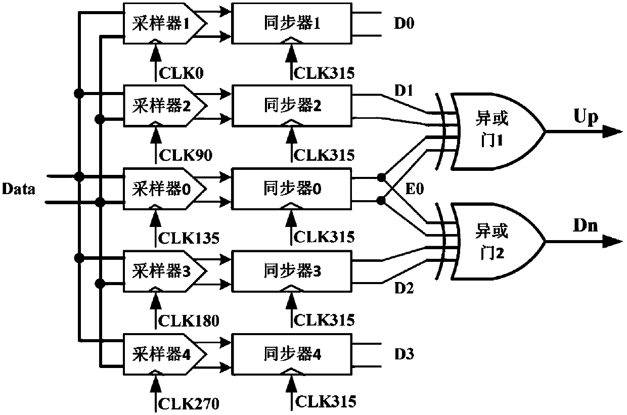
[0028] refer to figure 2 A Bang-Bang phase detector applied to a sub-rate clock data recovery circuit in this embodiment is specifically a Bang-Bang phase detector applied to a 1 / 4 rate clock data recovery circuit, that is, N=4.

[0029] The four data samplers used in this embodiment are respectively sampler 1, sampler 2, sampler 3 and sampler 4, and the four data synchronizers used are respectively synchronizer 1, synchronizer 2, synchronizer 3 and sampler 4. Synchronizer 4, the edge sampler at figure 2 Labeled as Sampler 0, the edge synchronizer is in figure 2 Marked as synchronizer 0, the two XOR gates are XOR gate 1 and XOR gate 2 respectively.

[0030] Sampler 1, sampler 2, sampler 3, and sampler 4 sample the input data Data under the action of data sampling clocks CLK0, CLK90, CLK180, and CLK270 with phases of 0, 90, 180, and 270, respectively. The input data Data is sampled under the action of the edge sampling clock CLK135 with a phase of 135. Synchronizer 1, Sy...


PUM


Abstract

The invention discloses a Bang-Bang phase discriminator for a sub-rate clock data recovery circuit. The Bang-Bang phase discriminator comprises multiple data samplers, an edge sampler, multiple data synchronizers, an edge synchronizer, and two XOR gates. The two XOR gates receive a retimed edge signal and a retimed data signal and then generate a leading voltage signal including phase difference information between a sampling clock and input data and a lagging voltage signal including phase difference information between the sampling clock and input data. The number of multiphase clocks required by the 1 / N rate Bang-Bang phase discriminator is decreased so that the jitter performance of the whole clock data recovery circuit is improved, and the operating frequencies of modules, such as the Bang-Bang phase discriminator and a voltage-controlled oscillator, in the clock recovery circuit are reduced.

Description

technical field [0001] The invention relates to the technical field of high-speed serial communication and high-speed analog integrated circuit, in particular to a Bang-Bang phase detector applied to a sub-rate clock data recovery circuit. Background technique [0002] Bang-Bang Phase Detector (BBPD), as an important module in Clock Data Recovery (CDR), is widely used in various high-speed serial communications, such as in Synchronous Optical Network (SONET), Passive Optical Network (PON) ) and 10 Gigabit Ethernet (10GbE) and other high-speed serial communication systems at the receiver side. The main function of the Bang-Bang phase detector is to detect the phase difference information between the input data and the sampling clock signal, and retiming to restore the data signal, but with the continuous increase of the data transmission rate (which has reached 10Gbps or even Higher), it is difficult for the receiving end to design a high-performance voltage-controlled oscil...

Claims


Application Information

Patent Timeline
Patent Type & Authority Patents(China)
IPC IPC(8): H03L7/08H03L7/095
CPCH03L7/0807H03L7/095
Inventor 黄森林福江周煜凯
Owner INST OF ADVANCED TECH UNIV OF SCI & TECH OF CHINA
Why Eureka
Try Eureka