A high-efficiency and low-load denitrification device and control method for thermal power units

A technology for control of thermal power units and devices, which is applied to electric controllers, separation methods, chemical instruments and methods, etc., can solve problems such as poor economy, damage to extraction valves, and large investment, achieve accurate and effective control methods, and reduce coal consumption for power generation. , the effect of improving cycle efficiency

Active Publication Date: 2018-09-25
ZHEJIANG ZHENENG TECHN RES INST
View PDF11 Cites 0 Cited by
  • Summary
  • Abstract
  • Description
  • Claims
  • Application Information

AI Technical Summary

Problems solved by technology

[0011] Aiming at the defects of the prior art, the purpose of the present invention is to provide a simple and reliable structure, no need for manual operation, high degree of automation, economical and environmental protection, and can overcome the influence of the economizer flue gas bypass on the boiler economy and easily lead to bypass blocking Leakage inside the plate, the use of economizer water supply bypass water supply changes have limited impact on the heat absorption of economizers, the use of economizers in hierarchical layouts requires a large investment and is difficult to implement, and the introduction of a high-parameter steam source replaces high-pressure heaters to heat steam pipes To increase the temperature of the feed water, the economy is poor and the frequent switching operation of the extraction valve is easy to cause damage and other shortcomings.

Method used


Image

  • A high-efficiency and low-load denitrification device and control method for thermal power units
  • A high-efficiency and low-load denitrification device and control method for thermal power units
  • A high-efficiency and low-load denitrification device and control method for thermal power units

Examples


Embodiment Construction

[0053] In order to make the object, technical solution and advantages of the present invention clearer, the present invention will be further described in detail below in conjunction with the accompanying drawings and embodiments. It should be understood that the specific embodiments described here are only used to explain the present invention, not to limit the present invention.

[0054] On the contrary, the invention covers any alternatives, modifications, equivalent methods and schemes within the spirit and scope of the invention as defined by the claims. Further, in order to make the public have a better understanding of the present invention, some specific details are described in detail in the detailed description of the present invention below. The present invention can be fully understood by those skilled in the art without the description of these detailed parts.

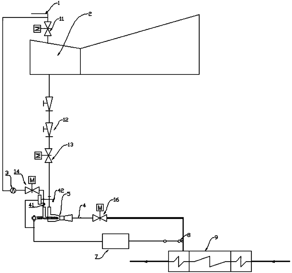
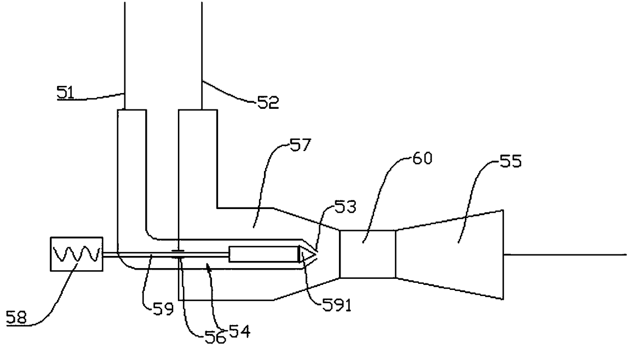
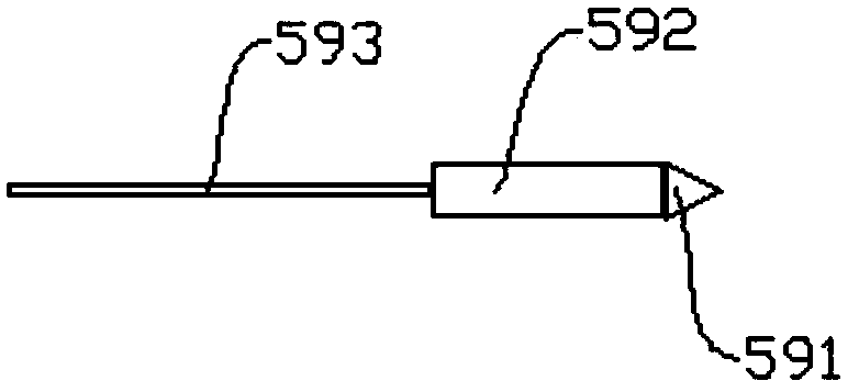
[0055] Such as Figure 1-3 As shown, a high-efficiency and low-load denitration device for a thermal ...


PUM


Abstract

The invention discloses a high-efficiency and low-load denitrification device and a control method for thermal power units, belonging to the field of denitrification control systems for large thermal power units. The flue temperature at the outlet of the economizer in the prior art cannot meet the minimum requirement for the flue gas temperature of the denitrification system for continuous ammonia injection. In the present invention, a matching device is set to adjust the pressure in the high-pressure heater to meet the temperature requirements of the feed water, increase the temperature of the flue gas at the SCR inlet, and meet the denitrification requirements of the unit under various working conditions. At the same time, due to the increase of feed water temperature, the cycle efficiency of the unit can be improved and the coal consumption of power generation can be reduced. The control method of the present invention uses a B-spline interpolation algorithm to fit the discrete data, and then can obtain a relatively accurate opening degree of the nozzle according to the known pressure difference, thereby improving the control precision of the control system. The control system uses the self-adaptive PID algorithm to fine-tune the opening of the nozzle, which can be adjusted in time according to the feedback, making the control method more accurate and effective.

Description

technical field [0001] The invention relates to a high-efficiency and low-load denitration device and a control method for thermal power units, belonging to the field of denitrification control systems for large thermal power units. Background technique [0002] The boiler denitrification devices of thermal power units in my country are all selective catalytic reduction (SCR). According to my country's environmental protection requirements, the denitrification devices of thermal power unit should be able to adapt to the low load of boilers between 50% and 100% BMCR to reduce the amount of gas in the smoke. emissions of nitrogen oxides. Due to the excess installed capacity of electricity in my country and the low demand for electricity, the current annual average load rate of thermal power units in my country is less than 60%, and most units operate for more than 2000 hours at 50% load. When the boiler is operating at a low load of 50% to 60%, the temperature of the flue gas ...

Claims


Application Information

Patent Timeline
Patent Type & Authority Patents(China)
IPC IPC(8): B01D53/90B01D53/56G05B11/42
CPCB01D53/8631B01D53/90B01D2251/2062G05B11/42
Inventor 罗海华谢尉扬周仁米顾伟飞董益华吴恒刚华敏赵佳俊朱宝赵卫正陈杰
Owner ZHEJIANG ZHENENG TECHN RES INST
Why Eureka
Try Eureka