
All-purpose vertical spinning machine with horizontally-arranged spinning rollers

A horizontal spinning machine technology, applied in the field of spinning machines, can solve problems such as uneven cooling and heating of brake hubs, explosions, cracks, cracks, etc., to achieve changing shape and thickness, improving tensile strength, and ingenious design Effect

Inactive Publication Date: 2016-11-09
泉州市泰智机械发展有限公司
View PDF6 Cites 3 Cited by
  • Summary
  • Abstract
  • Description
  • Claims
  • Application Information

AI Technical Summary

Problems solved by technology

At present, each part of the wheel has different requirements in the processing process. For example, for steel wheels, the spokes and rim parts are separated and welded into one body. There are various defects in the welding process, and there are defective rims in the butt welding link. , there are often phenomena such as explosions and cracks on the assembly line, which need to be repaired or scrapped; for the retaining ring groove of the steel rim, the existing technology is to use rolling technology to roll the flat plate to form the retaining ring groove; for the brake hub , most of the brake hubs in the prior art are integrally cast. During the driving process, due to continuous braking or wading, the brake hubs are unevenly cooled and hot to form cracks, and in severe cases, they will burst
At present, there is no spinning machine suitable for different workpieces in the wheel field on the market, and each workpiece must be processed by different equipment

Method used


Image

  • All-purpose vertical spinning machine with horizontally-arranged spinning rollers
  • All-purpose vertical spinning machine with horizontally-arranged spinning rollers
  • All-purpose vertical spinning machine with horizontally-arranged spinning rollers

Examples


Embodiment Construction

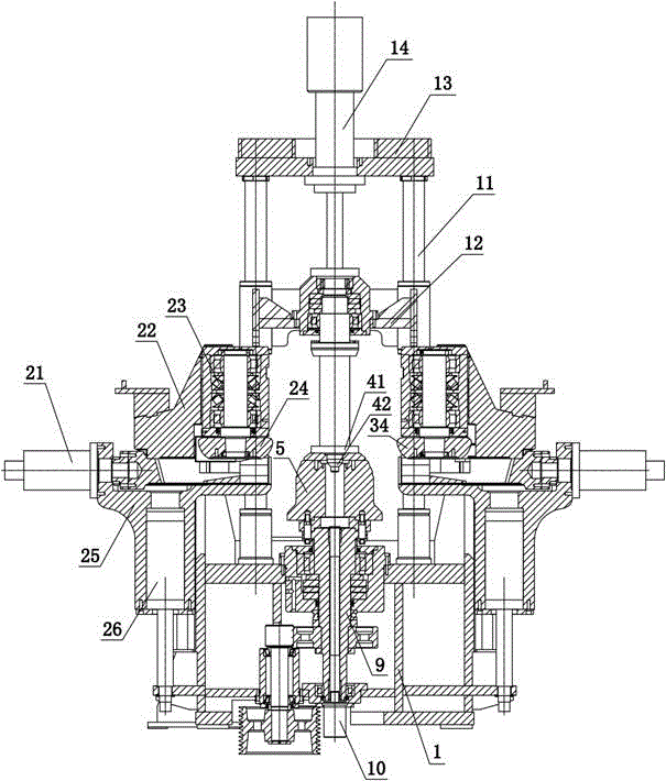
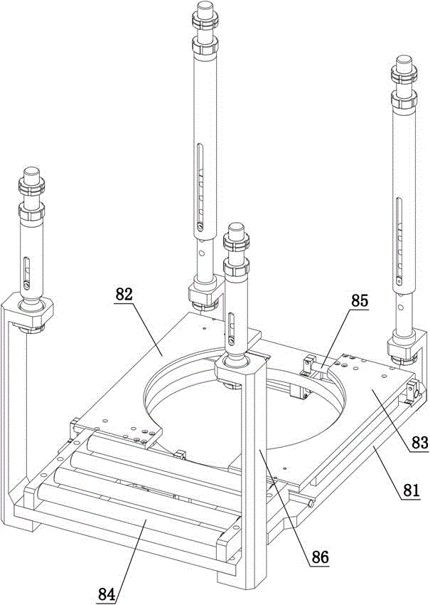
[0015] refer to figure 1 with figure 2 . Rotary flat universal vertical spinning machine, including base 1, coarse spinning mechanism 2, fine spinning mechanism 3, positioning and pressing seat 4, spinning mandrel 5, rough spinning profiling mechanism 6, fine spinning imitation Shape mechanism 7 and material holding mechanism 8. The rough rotation mechanism 2 and the fine rotation mechanism 3 are arranged on the left and right parts of the base 1 so that they can move left and right and can be lifted up and down respectively, and the coarse rotation mechanism 2 and the fine rotation mechanism 3 are arranged horizontally. The spinning mandrel 5 is arranged in the middle of the base 1 , and the positioning and pressing seat 4 is arranged above the spinning mandrel 5 . The top surface of the base 1 is provided with four columns 11 arranged in a square shape, the four columns 11 are provided with movable beams 12, and the top surfaces of the four columns 11 are fixedly provide...


PUM


Abstract

The invention discloses an all-purpose vertical spinning machine with horizontally-arranged spinning rollers. The all-purpose vertical spinning machine comprises a base, a rough spinning mechanism, a fine spinning mechanism, a location and compression seat, a spinning mandrel, a rough spinning profiling mechanism, a fine spinning profiling mechanism and a carrying mechanism, wherein the rough spinning mechanism and the fine spinning mechanism are arranged at the left part and the right part of the base respectively; the spinning mandrel is arranged at the middle part of the base; the location and compression seat is arranged above the spinning mandrel; four vertical columns are arranged on the top surface of the base; a movable beam is arranged on the four vertical columns in a sleeving manner; an upper beam is arranged on the top surfaces of the four vertical columns; a lifting oil cylinder is arranged on the upper beam; a piston rod of the lifting oil cylinder is fixedly connected with the top surface of the movable beam; the top end of the location and compression seat is fixedly connected with the bottom surface of the movable beam; the rough spinning profiling mechanism and the fine spinning profiling mechanism are arranged at the left part and the right part of the base; the carrying mechanism is arranged at the periphery of the spinning mandrel; a main shaft transmission mechanism is arranged at the middle part of the base; the spinning mandrel is connected to the top surface of the main shaft transmission mechanism; an ejection oil cylinder is arranged at the bottom of the base; and a piston rod of the ejection oil cylinder is capable of stretching out of the top surface of the spinning mandrel.

Description

technical field [0001] The invention relates to a spinning machine, in particular to a universal vertical spinning machine with a rotary wheel placed horizontally. Background technique [0002] The wheel is a rigid wheel that fixes the inner edge of the tire, supports the tire and bears the load together with the tire. It is mainly composed of spokes and rims. At present, each part of the wheel has different requirements in the processing process. For example, for steel wheels, the spokes and rim parts are separated and welded into one body. There are various defects in the welding process, and there are defective rims in the butt welding link. , there are often phenomena such as explosions and cracks on the assembly line, which need to be repaired or scrapped; for the retaining ring groove of the steel rim, the existing technology is to use rolling technology to roll the flat plate to form the retaining ring groove; for the brake hub , Most of the brake hubs of the prior a...

Claims


Application Information

Patent Timeline
IPC IPC(8): B21D22/16B21D45/02B21D43/00
CPCB21D22/16B21D43/003B21D45/02
Inventor 何玲许家地李泉峰
Owner 泉州市泰智机械发展有限公司
Learn More