Cutter for lathe machining of flat-bottom holes

A flat-bottom hole and turning technology, which is applied to the lathe tools, turning equipment, cutting blades, etc., can solve the problems of difficult chip removal, poor tool rigidity, and low efficiency, and achieve low manufacturing costs, guaranteed hole diameter, and tool structure. simple effect

Active Publication Date: 2016-11-09
CHINA ELECTRONIC TECH GRP CORP NO 38 RES INST
View PDF8 Cites 2 Cited by
  • Summary
  • Abstract
  • Description
  • Claims
  • Application Information

AI Technical Summary

Problems solved by technology

The processing efficiency of this method is acceptable when the hole diameter is small, but when processing flat-bottomed holes with larger diameters, the efficiency of this traditional processing method is very low, and the tool rigidity is poor and chip removal is difficult.

Method used


Image

  • Cutter for lathe machining of flat-bottom holes
  • Cutter for lathe machining of flat-bottom holes
  • Cutter for lathe machining of flat-bottom holes

Examples


Embodiment 1

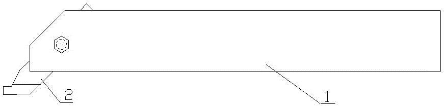
[0024] see figure 1 . A tool for turning flat-bottomed holes, comprising a tool holder 1 and a tool body 2 .

[0025] see figure 2 . The cutter bar 1 is a square body, and the front section of the cutter bar 1 is provided with an oblique square hole.

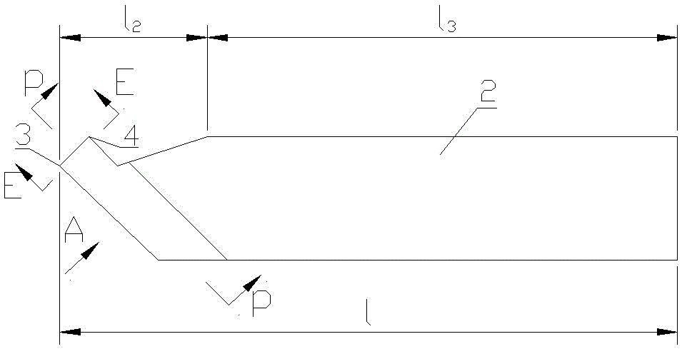
[0026] see image 3 . The cutter body 2 is a three-sided blade flat body turning tool installed in the oblique square hole of the cutter bar 1, and is fixed on the cutter bar 1 by bolts. The overall length l of the cutter body 2 is 65mm, including the edge groove portion l 2 and handle l 3 , handle l 3 The length of the blade is 45~55mm; 3 , including the working part and the non-working part, the length is 10-20mm.

[0027] see Figure 4 , Figure 5 , Image 6 . The rake angle of the tip of the cutter body 2 is 2°, and the relief angle α is 4-6°. The left and right sides of the front cutting edge 5 of the tip are the left cutting edge 6 and the right cutting edge 7, and the relief angle α1 of the left cutting ed...

Embodiment 2

[0031] The working principle of the present invention:

[0032] see Figure 7 , Figure 8 , Figure 9 . The front cutting edge 5 of the cutter body 2 performs longitudinal feed cutting parallel to the cutting spindle of the machine tool. At the same time, the front cutting edge 5 of the cutter body 2 starts from the inner diameter of the machined part for transverse feed cutting. The initial cutting rake angle is discharged from the arc groove between the cutting edge 6 and the right cutting edge 7, and the whole process of flat-bottomed hole machining is completed by feeding layer by layer, where α1 is related to the diameter of the inner hole to be processed, the smaller the inner hole diameter, The bigger α1 is.

[0033] In addition, some flat-bottomed holes need to have rounded corners at the root, and the left tip 3 and right tip 4 of the tool can be ground into a suitable rounded corner shape. Such knives are variants of the present special knives.


PUM


Abstract

The invention relates to a cutter for lathe matching of flat-bottom holes of discs. The cutter comprises a cutter bar and a cutter body. The cutter bar is a square strip, the cutter body is a three-edge flat lathe cutter fixedly mounted in an oblique square hole of the cutter bar. A left cutting edge and a right cutting edge are arranged on the left and right sides of a front cutting edge of the point of the cutter body, and an arc groove is arranged between the left and right cutting edges. The front cutting edge is set with an initial cut-in rake angle, an included angle between the initial cut-in rake angle and a front cutting edge rake angle is angle gamma, and the initial cut-in rake angle is connected with the arc groove between the left cutting edge and the right cutting edge. The cutter is simple in structure and high in strength of the cutter body; efficient machining of large-flat-bottom holes can be realized, and design requirements on aperture, roughness and the like are met effectively.

Description

technical field [0001] The invention relates to the technical field of cutting tools, in particular to a cutting tool for turning flat-bottomed holes of large discs. Background technique [0002] During the cutting process, we often encounter a large-diameter flat-bottomed hole on the workpiece. The usual processing method is to first drill a hole at the center of the flat-bottomed hole to be processed on the workpiece, and then gradually drill a hole from the center Machining of large diameter flat bottom holes to outer layer or turn boring. The processing efficiency of this method is acceptable when the hole diameter is small, but when processing flat-bottomed holes with larger diameters, the efficiency of this traditional processing method is very low, and the tool rigidity is poor and chip removal is difficult. Contents of the invention [0003] In view of the above-mentioned existing situation, the present invention provides a tool for turning flat-bottomed holes of ...

Claims


Application Information

Patent Timeline
Patent Type & Authority Applications(China)
IPC IPC(8): B23B27/00
CPCB23B27/005B23B2200/0423B23B2200/123B23B2200/286
Inventor 王建中王平郑杰瞿凌
Owner CHINA ELECTRONIC TECH GRP CORP NO 38 RES INST
Why Eureka
Try Eureka