Printing head for 3D printing, control system, 3D printer and printing method

A 3D printing and print head technology, applied in the direction of additive processing, etc., can solve the problems of reducing the self-weight, self-weight, and length of the print head, and achieve the effect of increasing the flexibility of movement, reducing the self-weight, and reducing the size.

Active Publication Date: 2016-11-09
浙江光镀智造科技有限公司
View PDF8 Cites 21 Cited by
  • Summary
  • Abstract
  • Description
  • Claims
  • Application Information

AI Technical Summary

Problems solved by technology

[0003] However, when large-scale industrial-grade 3D printers are used for printing, the existing printing head cannot adapt to various existing industrial materials, such as injection molding materials. If the printing head is to be adapted to various materials, it is necessary to use a feeding mechanism similar to an injection molding machine. However, the feeding mechanism of the injection molding machine is very heavy, and its own weight is very large; while the worktable of a large 3D printer is very large in size, if the worktable moves while the printing head does not move, the footprint of the 3D printer will increase by more than 4 times; The volume will also increase several times. Therefore, a large 3D printer needs to keep the workbench still while the print head moves. At this time, the self-weight of the print head will significant

Method used


Image

  • Printing head for 3D printing, control system, 3D printer and printing method
  • Printing head for 3D printing, control system, 3D printer and printing method
  • Printing head for 3D printing, control system, 3D printer and printing method

Examples


Example Embodiment

[0082] The embodiments of the present invention are described in detail below. Examples of the embodiments are shown in the accompanying drawings, in which the same or similar reference numerals indicate the same or similar elements or elements with the same or similar functions. The embodiments described below with reference to the accompanying drawings are exemplary, and are intended to explain the present invention, but should not be construed as limiting the present invention.

[0083] In the description of the present invention, it should be understood that the terms "center", "longitudinal", "transverse", "length", "width", "thickness", "upper", "lower", "front", " "Back", "Left", "Right", "Vertical", "Horizontal", "Top", "Bottom", "Inner", "Outer", "Clockwise", "Counterclockwise" and other directions or positions indicated The relationship is based on the orientation or positional relationship shown in the drawings, which is only for the convenience of describing the prese...


PUM


Abstract

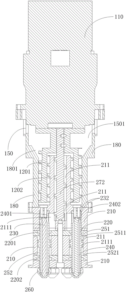
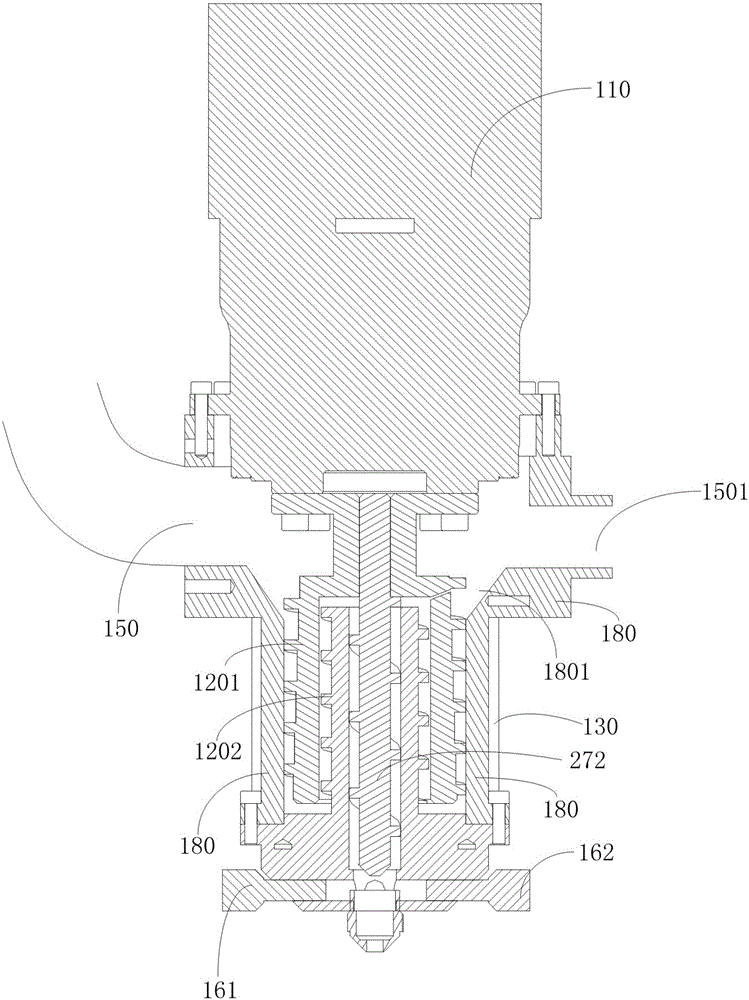
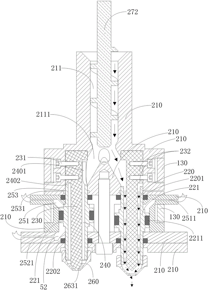
The invention discloses a printing head for 3D printing. The printing head comprises a machine shell, a screw extruding system, an installation seat, barrels, valve needles and spray nozzles. A drive system is arranged at one end of the machine shell. The screw extruding system is arranged in the machine shell and is composed of at least two screws which are embedded internally and externally, and at least one screw is driven by the drive system. The installation seat is mounted below the screw extruding system. One or more inner holes are distributed in the installation seat in the axial direction, and a discharge outlet is formed in the top or the side face of each inner hole. The barrels are mounted in all the inner holes of the installation seat correspondingly, the barrels extend out from one end of the installation seat, and barrel feeding openings are formed in the top ends of the barrels. Valve cavities are formed in the barrels. The valve needles penetrate through all the valve cavities of the barrels to be mounted on the installation seat, and the gaps between the valve needles and the valve cavities form discharging channels communicating with the feeding openings of the barrels. The spray nozzles are arranged at the tail ends of all the barrels. The printing head for 3D printing is light in weight, small in size, capable of achieving high printing precision and printing speed, novel in design, high in practicability and high in economic value.

Description

technical field [0001] The present invention relates to the technical field of 3D printing, in particular to a printing head for 3D printing, a control system for controlling the printing head for 3D printing, a 3D printer using the printing head for 3D printing and a printing method . Background technique [0002] 3D printing is a technology of manufacturing three-dimensional products by adding materials layer by layer through 3D printing equipment according to the designed 3D model. This layer-by-layer build-up forming technology is also called additive manufacturing. 3D printing integrates cutting-edge technologies in many fields such as digital modeling technology, electromechanical control technology, information technology, material science and chemistry. It is a kind of rapid prototyping technology and is known as the core technology of the "third industrial revolution". Compared with traditional manufacturing technology, 3D printing does not need to make molds in a...

Claims


Application Information

Patent Timeline
IPC IPC(8): B29C67/00B33Y30/00B33Y10/00B33Y50/02
CPCB33Y10/00B33Y30/00B33Y50/02
Inventor 陈名乔
Owner 浙江光镀智造科技有限公司
Why Eureka
Try Eureka