Automatically-controlled hydraulic material dividing device

A material distribution device and hydraulic device technology, applied in the direction of transportation and packaging, conveyors, conveyor objects, etc., can solve the problem of increasing operation time, increasing system energy consumption, and material flow that cannot accurately meet the needs of workshops or boiler materials, etc. question

Active Publication Date: 2016-11-09
NORTHERN HEAVY IND GRP CO LTD
View PDF5 Cites 3 Cited by
  • Summary
  • Abstract
  • Description
  • Claims
  • Application Information

AI Technical Summary

Problems solved by technology

Every reasonable suggestion or a change in detail will optimize the entire process flow. Due to the difference in incoming material capacity and reclaiming capacity (usually the incoming material capacity is greater than the reclaiming capacity), traditional methods often consider arranging multiple material strips , using the method of stocker stacking and reclaimer reclaiming, this process scheme cannot realize the function of the raw materials entering the factory directly to the workshop or boiler, and at the same time, the materials must pass through the work of the reclaiming equipment in the stockyard before the

Method used


Image

  • Automatically-controlled hydraulic material dividing device
  • Automatically-controlled hydraulic material dividing device

Examples


Embodiment Construction

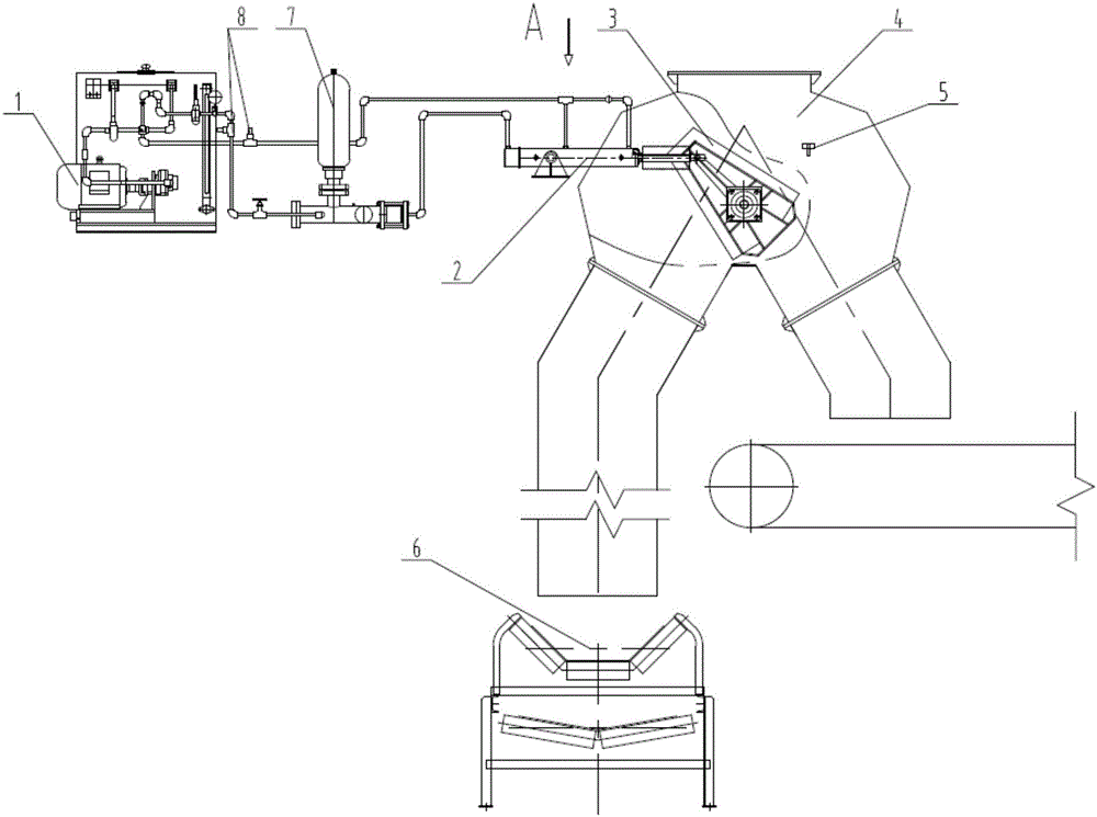
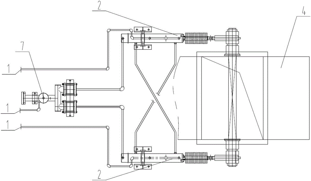
[0012] Referring to the accompanying drawings, an automatic control hydraulic material distribution device includes a hydraulic device 1, a transmission device 2, a material flow divider 3, a three-way body 4, a limit switch 5, a weighing tape machine 6, an impact stabilizer 7, and a locking adjustment The valve 8 and the material flow divider 3 are trapezoidal box structures, which are connected with the transmission device 2 through the rotating shaft. The main structure of the transmission device 2 is a hydraulic cylinder located on both sides of the three-way body 4. The hydraulic device 1 is closed with the transmission device 2 through the oil pipe. circuit, the position can be adjusted according to the actual working conditions on site, the impact stabilizer 7 and the lock regulating valve 8 are set on the oil circuit between the hydraulic device 1 and the transmission device 2, the weighing belt machine 6 is located at the bottom of the whole device, and the limit switch...


PUM


Abstract

An automatically-controlled hydraulic material dividing device comprises a hydraulic device, transmission devices, a material flow divider, a three-way body, limit switches, a weighing adhesive tape machine, an impact stabilizer and a locking adjusting valve; the material flow divider is of a trapezoid-like box structure and is connected with the transmission devices through rotation shafts, hydraulic cylinders located on the two sides of the three-way body serve as the main structures of the transmission devices, the hydraulic device and the transmission devices form a closed loop through oil pipes, the position can be adjusted according to the on-site actual work condition, the impact stabilizer and the locking adjusting valve are arranged on the oil way between the hydraulic device and the transmission devices, the weighing adhesive tape machine is located on the lower portion of the whole device, and the limit switches are welded to the external extreme positions of the two sides of the three-way body. According to the automatically-controlled hydraulic material dividing device, material flow dividing is automatically controlled and adjusted through the hydraulic device, the technological process that materials are directly conveyed into a workshop or a boiler is achieved, the pressure of the material site storage quantity is reduced, system energy consumption is reduced, the working efficiency is improved, and the automatically-controlled hydraulic material dividing device is applied to the technical field of bulk material conveying systems in the industries of ports, coal, electric power, metallurgy, mines and the like.

Description

technical field [0001] The invention relates to an automatic control hydraulic material distributing device in the technical field of conveying systems for bulk materials in industries such as ports, coal, electric power, metallurgy, and mines. Background technique [0002] At present, in the bulk material conveying system, the role of process layout is particularly prominent and important. Every reasonable suggestion or a change in detail will optimize the entire process flow. Due to the difference in incoming material capacity and reclaiming capacity (usually the incoming material capacity is greater than the reclaiming capacity), traditional methods often consider arranging multiple material strips , using the method of stocker stacking and reclaimer reclaiming, this process scheme cannot realize the function of the raw materials entering the factory directly to the workshop or boiler, and at the same time, the materials must pass through the work of the reclaiming equipm...

Claims


Application Information

Patent Timeline
IPC IPC(8): B65G47/72
CPCB65G47/72B65G2201/045
Inventor 冯松涛吴位民李勇袁麒计萱特王振江张琼哲张晓林朱占成王嘉男史哲
Owner NORTHERN HEAVY IND GRP CO LTD
Why Eureka
Try Eureka