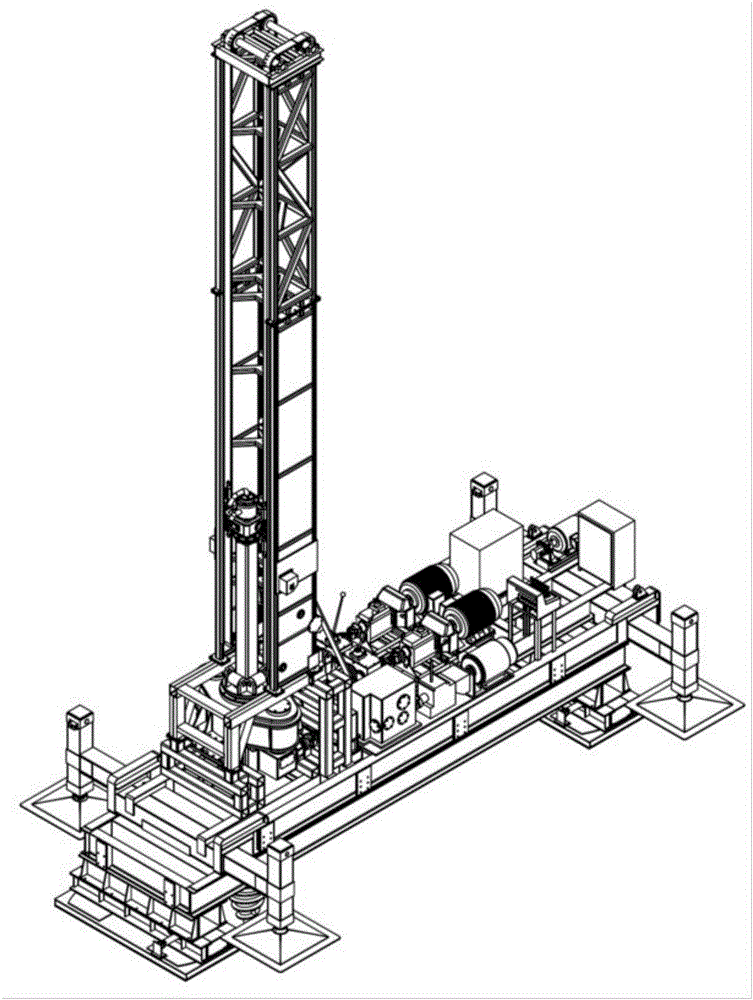
Double-row multi-shaft pile machine
A technology of pile driver and rotating head, which is applied in the field of double-row multi-axis pile driver, can solve the problems that have not been reported, and achieve the effects of good stability, reduced structural strength requirements, and reduced manufacturing costs
- Summary
- Abstract
- Description
- Claims
- Application Information
AI Technical Summary
Problems solved by technology
Method used
Image

Examples
Embodiment 1
[0038] Embodiment 1: Horizontal arrangement of I-shaped towers
[0039] When the I-shaped tower of a double-row multi-axis pile machine of the present invention is arranged horizontally, the pile types can be processed such as Figure 5 Shown, including: "before three and then three", "before three and then two", "before two and then three", "before two and then two", "before one and then two", "before two and then one" or "before one The beneficial effect of the double-row pile type with any combination of the latter "and other types is that it can adapt to the actual pile spacing array size requirements to the greatest possible extent when increasing the pile forming operation.
[0040] See attached Figure 2~4 , a double-row multi-axis pile driver, including: sprocket 1, I-shaped tower 2, two sets of lifting chains 3, six rotating heads 4, rotating head frame one 5 and rotating head frame two, six hollow drill rods 6. Six sets of lower-mounted square turntables, the lower...
Embodiment 2
[0054] Embodiment 2: Longitudinal arrangement of I-shaped towers
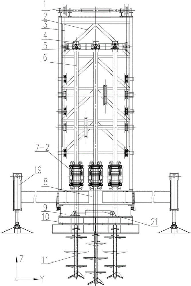
[0055] See attached Figure 6-8 , when the I-shaped tower 2 is vertically arranged, the pile types that can be processed include: "two in front and two in back", "two in front and two in front", "two in front and one in back" or "one in front and one in back" and other arbitrary combinations Double row pile type.
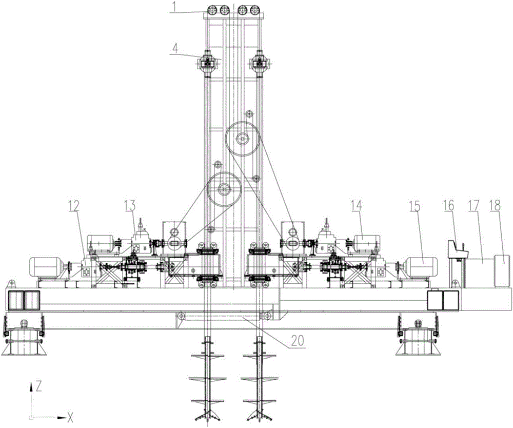
[0056] Layout of upper chassis 8, lower chassis 9, ram 10, longitudinal movement cylinder 20, transverse movement cylinder 21, four support legs 19, a set of hydraulic and electric operation table 16, hydraulic oil tank 17 and electric control cabinet 18 Same as Embodiment 1.
[0057] Setting: The horizontal direction of the double-row multi-axis pile machine is the Y-axis direction, the vertical direction is the X-axis direction, and the height is the Z-axis direction; Figure 8 In the I-shaped tower 2 shown, the neutral plane is parallel to the X axis.
[0058] See attached Figure 6-8 , when ...
PUM
 Abstract
Description
Claims
Application Information
 - R&D
- Intellectual Property
- Life Sciences
- Materials
- Tech Scout
- Unparalleled Data Quality
- Higher Quality Content
- 60% Fewer Hallucinations
Browse by: Latest US Patents, China's latest patents, Technical Efficacy Thesaurus, Application Domain, Technology Topic, Popular Technical Reports.
© 2025 PatSnap. All rights reserved.Legal|Privacy policy|Modern Slavery Act Transparency Statement|Sitemap|About US| Contact US: help@patsnap.com