Roller side movement cylindrical cam single-cylinder engine

A cylindrical cam and engine technology, which is applied in the direction of machines/engines, mechanical equipment, etc., can solve the problems of large volume, sudden change in speed, etc., and achieve the effects of prolonging life, reducing volume, and good hybrid expansion

Inactive Publication Date: 2016-11-09
ZHEJIANG UNIV
View PDF4 Cites 5 Cited by
  • Summary
  • Abstract
  • Description
  • Claims
  • Application Information

AI Technical Summary

Problems solved by technology

[0004] In order to overcome the shortcomings of the existing internal combustion engine piston connecting rod mechanism, such as the sudden change in speed at the top and bottom dead centers, the al...

Method used


Image

  • Roller side movement cylindrical cam single-cylinder engine

Examples


Embodiment Construction

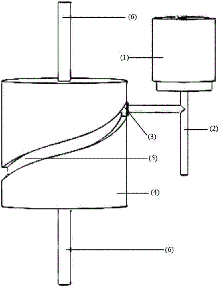
[0014] The invention provides a roller side-moving cylindrical cam single-cylinder engine, which includes a piston 1 connected with a push rod 2, and a cylindrical cam 4 (cam rotor). A power shaft 6 is fixed on the cylindrical cam 4, and the outer side of the cylindrical cam 4 is A cam chute 5 is provided; the push rod 2 side of the piston 1 is provided with a side rod with a roller 3 at the top, and the push rod 2 is placed next to the cylindrical cam 4, and the push rod 2 is always in line with the cylindrical cam when it moves linearly. 4 The relative position remains unchanged. The roller 3 moves in the cam slideway 5, and the linear reciprocating motion of the piston push rod 2 is converted into a rotary motion through the cylindrical cam 4. Both ends of the cylindrical cam 4 are respectively fixed with power shafts 6 .

[0015] The cam sliding groove 5 is a cosine curve.

[0016] exist figure 1 In the process, the piston 1 pushes the push rod 2 for linear motion. The...


PUM


Abstract

The invention relates to internal combustion engine devices, in particular to a roller side movement cylindrical cam single-cylinder engine. The roller side movement cylindrical cam single-cylinder engine comprises a piston connected with a push rod and further comprises a cylindrical cam. A power shaft is fixed to the cylindrical cam. A cam sliding groove is formed in the outer side of the cylindrical cam. A side rod is arranged on one side of the push rod of the piston, and a roller is arranged at the top end of the side rod. The roller moves in the cam sliding groove, and linear back-and-forth movement of the push rod of the piston is converted into rotation movement through the cylindrical cam. Continuous changes of a roller acceleration curve are achieved through the cam outline, that is, sudden change impact does not occur when the roller is in the upper dead center and the lower dead center. A cam rotor can be used as a flywheel of a traditional internal combustion engine, so that a flywheel structure is omitted, and the size of the engine is reduced. The push rod of the piston is always kept on the side portion of the cam, and the position is unchanged relatively, so that loads borne by the piston are not alternating side pressure. Accordingly, the service life of the piston and the push rod is greatly prolonged.

Description

technical field [0001] The invention relates to an internal combustion engine device, in particular to a power transmission system of the internal combustion engine, in particular to a cylindrical cam single-cylinder engine with side-moving rollers. Background technique [0002] The internal combustion engine mixes fuel and air and burns it in its cylinder, and the heat energy released makes the cylinder generate high-temperature and high-pressure gas. The expansion of the gas pushes the piston to do work, and then the mechanical work is output through the crank connecting rod mechanism or other mechanisms to drive the driven machine to work. [0003] At present, there are still many deficiencies in the internal combustion engine. First, there is a sudden change in the speed direction of the piston of the engine when it is at the top and bottom dead centers. Alternating side pressure seriously affects the service life of push rods and pistons; finally, the existing engine s...

Claims


Application Information

Patent Timeline
IPC IPC(8): F02B75/16F02B75/32
CPCF02B75/16F02B75/32
Inventor 申恩恩李康熊树生许印川郭越王宇杨兴浩万波王亚彬滕志峰
Owner ZHEJIANG UNIV
Why Eureka
Try Eureka