Hydraulic control loop for garbage truck

A control circuit and hydraulic technology, applied in fluid pressure actuation devices, fluid pressure actuation system components, servo motors, etc., can solve the problems of rising load pressure, easy failure of seals, and aggravated wear between parts, so as to reduce jamming Possibility of valve, improvement of heat dissipation effect, effect of reducing motion shock

Inactive Publication Date: 2016-11-09
杭州华泰电液成套技术有限公司
View PDF6 Cites 20 Cited by
  • Summary
  • Abstract
  • Description
  • Claims
  • Application Information

AI Technical Summary

Problems solved by technology

The circuit between the oil source and the actuator contains many directional valves and throttle valves to achieve different working conditions, but the number of valves is often set too much, resulting in a large throttling loss; the throttle valve is used as a back pressure valve. When the load changes greatly, the load pressure rises and the power consumption increases
[0006] 2. Serious oil pollution
Due to the harsh working environment of garbage trucks, pollutants can easily enter the oil circuit through the piston rod of the cylinder and the air filter, and the hydraulic oil is easily polluted. Severe oil pollution wi

Method used


Image

  • Hydraulic control loop for garbage truck
  • Hydraulic control loop for garbage truck
  • Hydraulic control loop for garbage truck

Examples


Embodiment Construction

[0034] The present invention will be further described below in conjunction with embodiment and accompanying drawing.

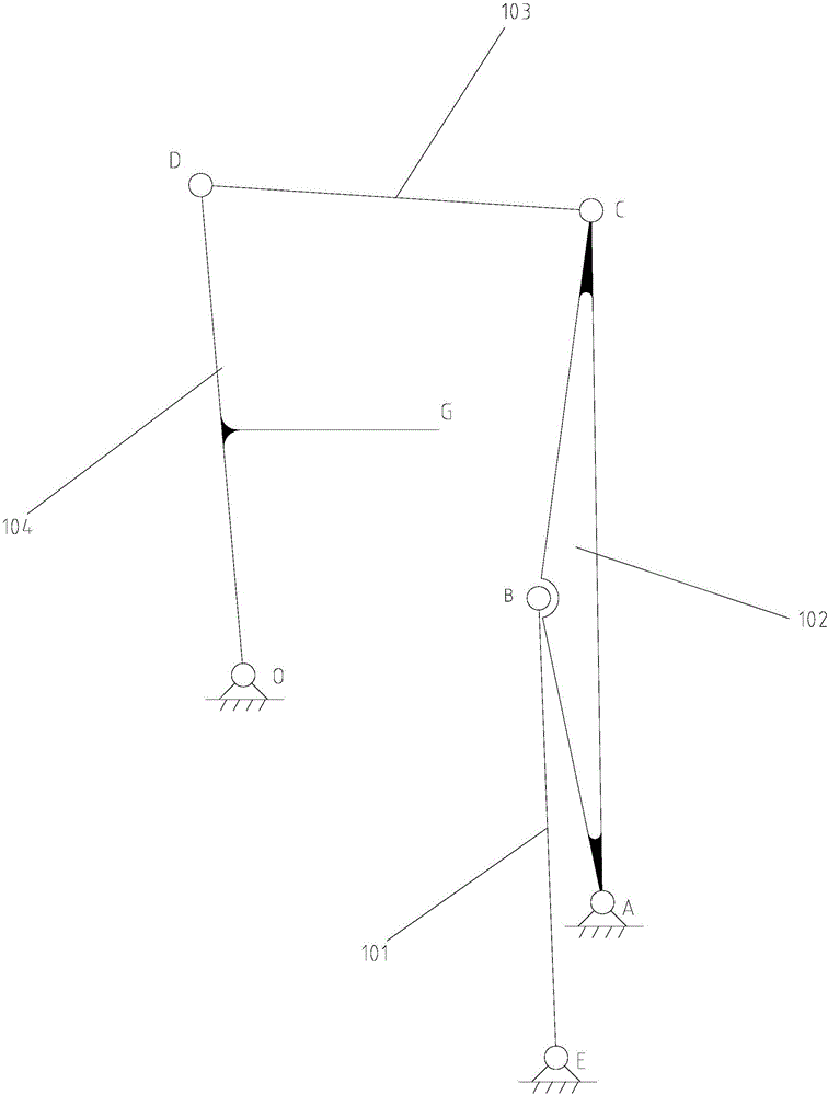
[0035] Such as figure 1The above is a schematic structural diagram of the feeding mechanism of the intelligent garbage truck. One end E of the cylinder piston rod is a fixed end, which is hinged with the vehicle body frame, and the other end B is the movable end of the piston rod, which is hinged with the swing rod 102. , one fixed end A of the swing rod 102 is hinged with the vehicle body frame, the other fixed end C is hinged with one end of the connecting rod 103, the other fixed end D of the connecting rod 103 is hinged with a fixed end of the hopper, and the hopper is simplified as A pendulum is hinged with the O end on the frame and can rotate around the O end. Point G is the center of gravity of the hopper. The position of the hopper 104 in the figure is the position when the lifting is complete. At this time, the position of the cylinder piston rod 10...


PUM


Abstract

The invention provides a hydraulic control loop for a garbage truck. The hydraulic control loop is composed of an oil source, an oil path integration block and an actuator. The oil source comprises a metering pump, an air cooler, a returned oil filter and other hydraulic auxiliary components. The oil path integration block comprises a high-pressure filter, an electromagnetic reversing valve, a balance valve and an overflow valve. The actuator comprises a feeding hydraulic cylinder set and a material pressing hydraulic cylinder set. The high-pressure filter, the electromagnetic reversing valve, the balance valve, the overflow valve, the feeding hydraulic cylinder set in the hydraulic oil source oil path integration block are sequentially connected through a pipeline to form a hopper feeding control loop, and are connected with the material pressing hydraulic cylinder set to form a material pressing control loop. According to the system, the number of the valves in the oil path integration block is reduced, the throttling loss is reduced, and the energy saving is achieved. A main oil path is internally provided with the high-pressure filter to guarantee cleanliness of oil liquid, and blockage of the valve is avoided. A returned oil path is provided with the air cooler, and heat dissipation of the system is improved. A hydraulic lock and a flow valve are replaced with the bi-directional balance valve, the self-locking function is achieved, and the stability of hopper moving of the garbage truck is guaranteed.

Description

technical field [0001] The invention relates to a hydraulic control circuit for a garbage truck, belonging to the technical field of hydraulic control systems. Background technique [0002] Garbage trucks are sanitation vehicles used to collect and transport garbage, and are used in municipal sanitation work and garbage transportation in factories and mines. Traditional garbage trucks require artificial filling, which is sent into the car body for compression. In recent years, with the wide application of computer technology, modern control theory, and electronic technology, garbage trucks have gradually become intelligent. Intelligent garbage trucks integrate garbage loading, compression, and transportation, and partially realize the automation of operation control, reducing unnecessary waste. of human intervention. [0003] The intelligent garbage truck is mainly composed of a car chassis, a carriage, a feeding mechanism, a pressing mechanism, and a hydraulic circuit con...

Claims


Application Information

Patent Timeline
IPC IPC(8): F15B11/16F15B21/04F15B13/06
CPCF15B11/16F15B13/06F15B21/041F15B21/042
Inventor 张超尹天力
Owner 杭州华泰电液成套技术有限公司
Why Eureka
Try Eureka