End butt joint type loop heat pipe

A docking and looping technology, applied in the field of heat pipes, can solve the problems of difficult manufacturing, processing and forming, inconsistent with industrial economic benefits, and reduced heat dissipation efficiency.

Inactive Publication Date: 2016-11-09
SUZHOU FORCECON ELECTRIC
View PDF1 Cites 0 Cited by
  • Summary
  • Abstract
  • Description
  • Claims
  • Application Information

AI Technical Summary

Problems solved by technology

[0002] In view of the internal structure design of the early heat pipe, the steam flow path and the condensate flow path were arranged in the same pipe section space and were arranged in an overlapping state, so that the flow directions conflicted with each other and hindered each other, resulting in reduced heat dissipation efficiency and other problems. The industry has developed a loop-type heat pipe structure. In this heat pipe structure, the steam flow path and the condensate flow path are set in different sections in the heat pipe space, and the overall form of a loop form can solve the aforementioned problems.
[0003] However, the existing loop-type heat pipe structure that can be seen at present still has its shortcomings. The two ends are spaced apart from each other, and a base is set between the two ends. The base is provided with a connecting channel, and the two ends of the pi

Method used


Image

  • End butt joint type loop heat pipe
  • End butt joint type loop heat pipe
  • End butt joint type loop heat pipe

Examples


Embodiment

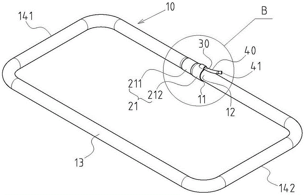
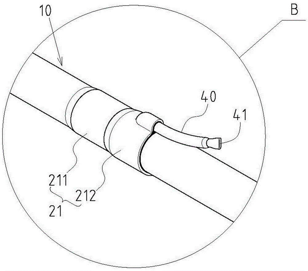
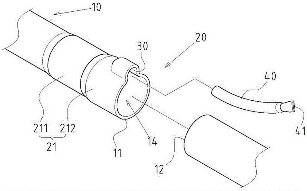
[0025] Example: see Figure 1~4 Shown is the preferred embodiment of the end-butt loop heat pipe of the present invention, but these embodiments are for illustration purposes only, and are not limited by this structure in patent application.

[0026] The end-butt loop type heat pipe includes the following components: a loop-type tube body 10, which is formed by a hollow tube body, and its exterior is bent into a folded shape to include a first tube end 11, a second tube end 12 and a loop-type segment 13 between the first pipe end 11 and the second pipe end 12, the inside of the loop-type pipe body 10 forms a loop-type flow passage space 14, and the loop-type flow passage space 14 includes an evaporating section 141 and a condensing section 142. The loop-type flow channel space 14 is in a vacuum-enclosed state and accommodates a working fluid 143, and a capillary section is provided between the evaporating section 141 and the condensing section 142. Tissue 144 (it can be a met...


PUM


Abstract

The invention provides an end butt joint type loop heat pipe which is mainly being characterized by comprising a loop pipe body, an inserting and sleeving type butt joint part, an inserting gap and a degassing pipe. The outside of the loop pipe body is bent into a hollow square shape, and the loop pipe body comprises a first pipe end, a second pipe end and a loop section. The inserting and sleeving type butt joint part is formed in the manner that the first pipe end and the second pipe end of the loop pipe body serve as an inner pipe and an outer pipe to be inserted and sleeved oppositely in a sealed manner, and any one of the first pipe end and the second pipe end is arranged in the manner that the pipe diameter is enlarged, and provided with a pipe enlarging part. The inserting gap is formed at the position of the radial local part between the first pipe end and the second pipe end, and penetrates the outside of the inserting and sleeving type butt joint part and a loop flow pass space in the loop pipe body. The degassing pipe is inserted into the inserting gap in a close fit manner to serve as a vacuumizing and working solution pouring channel, and the outer end of the degassing pipe extends out of the inserting and sleeving type butt joint part and is provided with a closed part. The structure of the loop heat pipe can achieve practical progress of member simplification, easier and faster manufacturing, machining and forming and substantial manufacturing cost reduction, and achieve better industrial economy benefits.

Description

technical field [0001] The invention relates to a heat pipe, in particular to an innovative butt-connected loop heat pipe structure. Background technique [0002] In view of the internal structure design of the early heat pipe, the steam flow path and the condensate flow path were arranged in the same pipe section space and were arranged in an overlapping state, so that the flow directions conflicted with each other and hindered each other, resulting in reduced heat dissipation efficiency and other problems. The industry has developed a loop-type heat pipe structure. In this heat pipe structure, the steam flow path and the condensate flow path are set in different sections in the heat pipe space, and form a loop form as a whole, so as to solve the aforementioned problems. [0003] However, the existing loop-type heat pipe structure that can be seen at present still has its shortcomings. The two ends are spaced apart from each other, and a base is set between the two ends. T...

Claims


Application Information

Patent Timeline
IPC IPC(8): F28D15/04
CPCF28D15/043F28D15/046
Inventor 何信威黄志仁
Owner SUZHOU FORCECON ELECTRIC
Why Eureka
Try Eureka