Micro-current measurement method

A measurement method and micro-current technology, applied in the direction of measurement device, measurement of electrical variables, measurement of current/voltage, etc., to achieve the effect of improving the signal-to-noise ratio

Inactive Publication Date: 2016-11-09
JIANGNAN UNIV
View PDF5 Cites 6 Cited by
  • Summary
  • Abstract
  • Description
  • Claims
  • Application Information

AI Technical Summary

Problems solved by technology

[0003] In order to solve the micro-current measurement problem with a minimum measurement range

Method used


Image

  • Micro-current measurement method
  • Micro-current measurement method
  • Micro-current measurement method

Examples


Example Embodiment

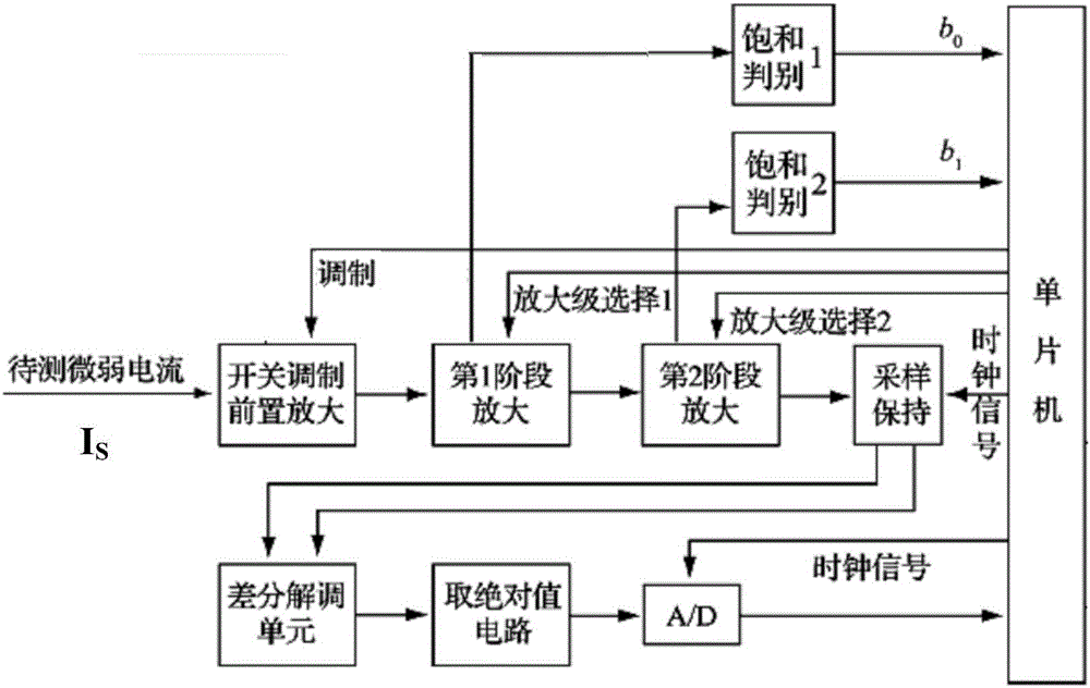
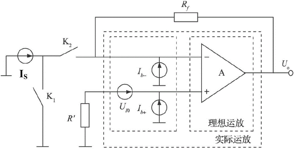
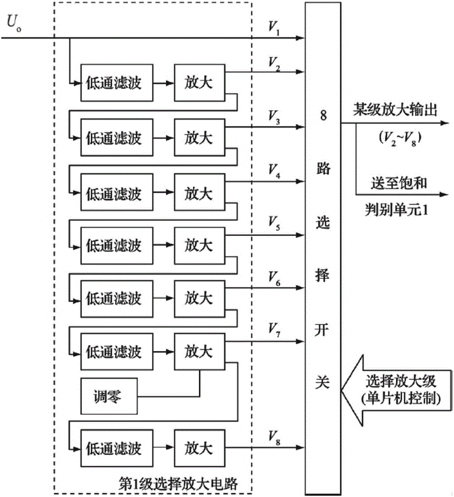
[0020] The specific embodiments of the present invention will be further described below in conjunction with the drawings.

[0021] Weak signal detection is to filter out the interference signal from the signal source, enhance and restore the useful signal to be measured to the maximum extent, improve the signal-to-noise ratio (SNR), and effectively suppress noise is the difficulty and key point of the micro-current measurement. According to the types and characteristics of noise, there are two main sources: 1) inherent noise from the electronic system, including the bias current and offset voltage of the op amp, the thermal noise generated by the heating of electronic components, and the impulse noise generated by the interference of digital circuits. Spike noise generated by the switching circuit, etc.; 2) From outside the electronic system, such as power frequency interference, radio frequency noise, atmospheric noise, mechanical noise, etc. In the measurement, the processing ...


PUM


Abstract

The invention discloses a micro-current measurement method. At first, micro-current is modulated and amplified at a pre-amplification stage, and then, microcurrent signals are converted into micro-voltage signals; and the microcurrent signals are amplified through two stages. Each stage is provided with multi-stage amplifiers; a single-chip microcomputer controls a plurality of selective switches and makes the same switched on sequentially; multi-stage amplification signals are sent to a saturation judgment circuit; the saturation judgment circuit carries out judgment; when output signals exceed the linear range of the work of an operational amplifier for the first time, the single-chip microcomputer provides amplification stage selection signals; the current stage is switched to a lower stage; the signals at the current stage are send to the next stage; modulation switches carry out sampling holding on the amplified voltage signals; system error is removed through a differential circuit; and voltage signals which are in direct proportion to the measured microcurrent are outputted. According to the microcurrent measurement method of the invention, switching modulation, low-pass filtering, operational amplification feedback, multi-stage amplification, differencing and state distinguishing circuits are adopted to constitute the whole measurement system, and therefore, the signal-to-noise ratio of the measurement system can be improved.

Description

technical field [0001] The invention relates to the field of micro-signal detection, in particular to a micro-current measurement method. Background technique [0002] With the development of science and technology, experimental measurement under extreme conditions has become an important means to further understand nature. These experiments often measure some very weak physical quantities, such as weak magnetism, weak sound, weak light, weak vibration, etc. Due to These weak signals are generally converted into electric power by sensors, so that the weak signals to be measured are converted into electrical signals. In actual measurement, noise and interference cannot be avoided, which affects the sensitivity and accuracy of measurement. For pA-level current measurement, the measurement circuit cannot directly capture the current signal, and I / U conversion is required. The converted voltage signal needs to be further amplified, otherwise it will be interfered by DC signals...

Claims


Application Information

Patent Timeline
IPC IPC(8): G01R19/25
CPCG01R19/2506
Inventor 潘丰沈蒙
Owner JIANGNAN UNIV
Why Eureka
Try Eureka