Dual polarization radar arbitrary polarization wave on-line calibrating method

A calibration method and polarized wave technology, applied in radio wave reflection/re-radiation, radio wave measurement system, using re-radiation, etc., can solve large errors, inability to modulate radio frequency signals, insufficient polarization purity of polarized waves, etc. question

Active Publication Date: 2016-11-09
CNGC INST NO 206 OF CHINA ARMS IND GRP
View PDF5 Cites 25 Cited by
  • Summary
  • Abstract
  • Description
  • Claims
  • Application Information

AI Technical Summary

Problems solved by technology

However, the current domestically developed dual-polarization weather radars generally have the problem of poor polarization measurement accuracy, which leads to misjudgment of the shape of meteorological particles and affects the promotion and application of dual-polarization weather radars in China.
There are two main reasons for the error in polarization measurement. One is that the polarization purity of the emitted polarized wave is not enough.
Ferrite devices are generally used in China to adjust the phase and amplitude of radio frequency polarized waves. This technology is difficult to ensure the polarization characteristics of polarized waves, and is easily affected by factors such as temperature and environment.
Second, the stability of the radar system itself is not enough, and the consistency of the two channels is not enough
First, the analog system is susceptible to environmental temperature changes, and its attenuation cannot be accurately controlled, especially when the attenuation step i

Method used


Image

  • Dual polarization radar arbitrary polarization wave on-line calibrating method
  • Dual polarization radar arbitrary polarization wave on-line calibrating method
  • Dual polarization radar arbitrary polarization wave on-line calibrating method

Examples


Embodiment Construction

[0032] Now in conjunction with embodiment, accompanying drawing, the present invention will be further described:

[0033] 1. Polarization control

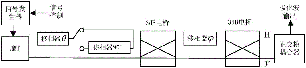
[0034]The on-line calibration technology of dual-polarization radar requires the ability to generate various required polarization calibration signals, that is, to continuously adjust the amplitude and phase of the two orthogonal polarization signals, and synthesize arbitrary polarization waves. For this reason, the polarized wave control method used in the present invention will be introduced first.

[0035] Such as figure 2 As shown, the transmission signal generated by the radar transmitter or signal generator is divided into two channels by the magic T (MT). The upper arm of the magic T is connected in series with a phase-shift controller θ, and the two signals are synthesized by a 3dB bridge. Another phase-shift controller is connected in series on one arm of another 3dB bridge When the phase θ of the phase shifter and ...


PUM


Abstract

The invention relates to a dual polarization radar arbitrary polarization wave on-line calibrating method. A polarization calibrating channel is constituted by a digital calibrating unit, a digital-to-analog converter, a frequency converter, a calibrating horn, a main feed source horn, and a receiving channel. The digital calibrating unit is substantially an arbitrary waveform generator, and is used to generate standard continuous wave sinusoidal signals, noise signals, arbitrary digital waveforms, and delay of emission signal transcripts. When a polarization radar works in a calibrating mode, an output end of an emitter is used to couple a few of signals, which are used as transcripts of the emission signals. The signals are converted into digital signals after down conversion operation, filtering operation, and ADC conversion operation, and are used as digitalized emission sampling signals, which are input in the digital calibrating unit. After the amplitude conversion processing, the phase conversion processing, the frequency spectrum conversion processing, the delay conversion processing, and other conversion processing of the signals in a numerical field, the signals are converted into analog signals, and the analog signals are converted into radio frequency signals by up conversion operation, and then are irradiated on a main feed source by the calibrating horn.

Description

technical field [0001] The invention is applied in the technical field of dual-polarization weather radar, and the method can be used to calibrate the state and characteristics of any polarized wave in real time, thereby improving the measurement accuracy of the polarized radar. Background technique [0002] The main application of polarimetric radar is target recognition, and its technical basis is the measurement of the polarization characteristics of the target by radar, including the analysis and measurement of the target polarization scattering matrix and electromagnetic wave polarization parameters. With the successful application of dual-polarization radar in meteorological detection and meteorological particle identification, dual-polarization radar has gained wide recognition and application prospects in the field of meteorological particle (hail, haze, etc.) detection and artificial weather modification. [0003] In recent years, research and production institution...

Claims


Application Information

Patent Timeline
IPC IPC(8): G01S7/40G01S13/95
CPCG01S7/4052G01S13/95G01S7/4065Y02A90/10
Inventor 魏志强李春化闫兴伟苏小敏李重阳陈明周子超王乐
Owner CNGC INST NO 206 OF CHINA ARMS IND GRP
Why Eureka
Try Eureka