Multichannel fluorescent microscopy composite microscopic system

A microscopic system and multi-channel technology, applied in the field of microscopy, can solve problems such as cost increase and difficult operation, and achieve the effect of reducing scientific research costs and improving instrument utilization

Active Publication Date: 2016-11-09
宁波力显智能科技有限公司
View PDF5 Cites 13 Cited by
  • Summary
  • Abstract
  • Description
  • Claims
  • Application Information

AI Technical Summary

Problems solved by technology

The first challenge is that the scale of the observed content in the studied samples is getting smaller and smaller. The size of cells is on the order of ten microns, the size of organelles such as mitochondria and chloroplasts is on the order of microns, and the size of vesicles in cells is on the order of hundreds to several On the order of ten nanometers, the size of most proteins is less than 50 nanometers. To clearly see the life structure on these scales, the spatial resolution of the fluorescence microscope is very high.
The second challenge is the

Method used


Image

  • Multichannel fluorescent microscopy composite microscopic system
  • Multichannel fluorescent microscopy composite microscopic system

Examples


Embodiment 1

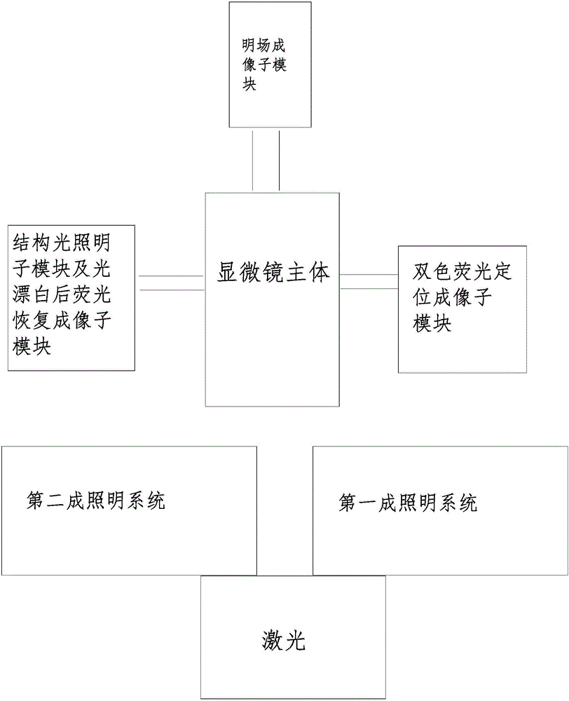
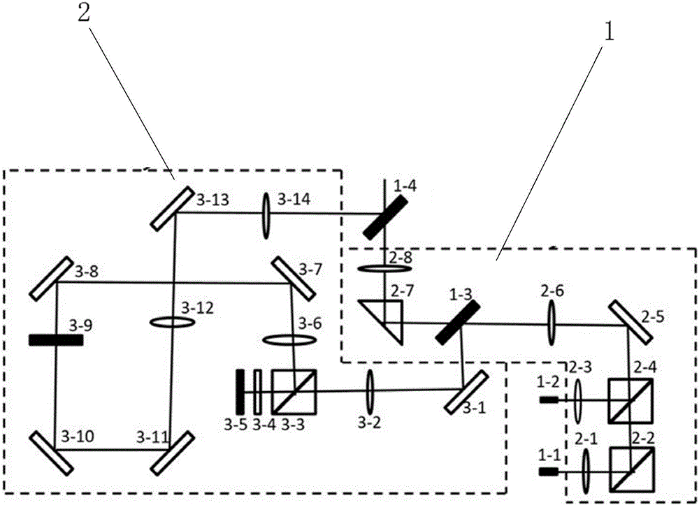
[0029] figure 1 The present invention includes a microscope main body, a SCMOS or EMCCD camera, and a composite lighting module, which includes a light source and a bright field light lighting submodule, a two-color fluorescent positioning lighting submodule, a structured light lighting submodule, and a fluorescence recovery function after photobleaching Lighting sub-module. The light source enters into the microscope main body through each illumination sub-module, and irradiates on the sample. The sample selection is mapped on the bright field imaging sub-module, the two-color fluorescence localization imaging sub-module, the structured light illumination imaging sub-module and the fluorescence recovery imaging sub-module after photobleaching. figure 2 The two-color fluorescent positioning lighting submodule and the bright field light lighting submodule are in the first lighting system 1, the structured light lighting submodule and the fluorescent recovery function lighting...

Embodiment 2

[0034] The imaging modes of the composite microscope system are: bright field imaging (high temporal resolution, large field of view); two-color fluorescence localization imaging (high spatial resolution xy direction 20nm, y direction 50nm); structured light illumination imaging (high spatial resolution xy 100nm in direction, 500nm in y direction; high temporal resolution of about 360ms per frame, imaging range of 2048*2048 pixels; high signal-to-noise ratio); fluorescence recovery imaging after photobleaching; simultaneous imaging of bright field and two-color fluorescence positioning; bright field and structured light Simultaneous imaging under illumination; Simultaneous imaging of bright field and fluorescence recovery after photobleaching. These six imaging modes can be conveniently selected by software.


PUM


Abstract

The invention provides a multichannel fluorescent microscopy composite microscopic system, and belongs to the technical field of microscopes. The multichannel fluorescent microscopy composite microscopic system comprises a microscope body, an imaging module and a composite lighting module. A mechanical rotating mirror is controlled to change the light path of the composite lighting module through a control system, and light matched with the imaging module and modulated through different modes is selected to enter the microscope body by the mechanical rotating mirror to perform lighting on a sample. The device has four functions including a two-color fluorescent localization microscopic function, a structured light lighting microscopic function, a function of fluorescent recovery after photobleaching and a bright field imaging function respectively. The appropriate method can be selected to perform high spatial resolution or high time resolution imaging on the sample in a bioexperiment according to the characteristics of the sample and the imaging requirements, and different modes of imaging can be performed on the same position of the same sample so that the problem of one-sidedness of the imaging result of the single microscopic method can be solved.

Description

technical field [0001] The invention belongs to the technical field of microscopes, in particular to a composite microscope system for multi-channel fluorescence microscopy. Background technique [0002] Biomicroscopy plays a pivotal role in the research of life science and technology, and with the development and refinement of research on life processes, biomicroscopy has encountered more and more challenges. The first challenge is that the scale of the observed content in the studied samples is getting smaller and smaller. The size of cells is on the order of ten microns, the size of organelles such as mitochondria and chloroplasts is on the order of microns, and the size of vesicles in cells is on the order of hundreds to several On the order of ten nanometers, the size of most proteins is less than 50 nanometers. To clearly see the life structure on these scales, the spatial resolution of the fluorescence microscope is highly required. The second challenge is the real-t...

Claims


Application Information

Patent Timeline
IPC IPC(8): G02B21/06G02B21/36
CPCG02B21/06G02B21/36
Inventor 王莹
Owner 宁波力显智能科技有限公司
Why Eureka
Try Eureka