

Manufacturing method of luneberg lens antenna
A technology of Lunberg lens antenna and manufacturing method, which is applied to antennas, electrical components, etc., can solve the problems of the deviation of the dielectric constant of the lens layer and the design value, the influence of the working performance of the lens antenna, and the deviation of the change of the dielectric constant, etc., and achieve compactness. High, structural integrity, uniform density effect
Inactive Publication Date: 2016-11-09
深圳贝斯特网联通讯设备有限公司
View PDF3 Cites 18 Cited by
- Summary
- Abstract
- Description
- Claims
- Application Information
AI Technical Summary
Problems solved by technology
However, in the production process of the traditional Lunberg lens antenna, the dielectric constant of each lens layer generally has defects that are difficult to control, which leads to a large deviation between the dielectric constant of each lens layer and the design value, resulting in the production of the Lunberg. The variation of the dielectric constant of the Lunberg lens deviates from the ideal change law, which eventually leads to the serious impact on the performance of the lens antenna assembled by the Lunberg lens
Method used
View moreImage
Smart ImageViewing Examples

Examples
Embodiment 1
[0072]
[0073]
Embodiment 2
[0075]
[0076]
[0077]
Embodiment 3
[0079]
[0080]
Login to View More PUM
| Property | Measurement | Unit |
|---|---|---|
| Thickness | aaaaa | aaaaa |
Abstract
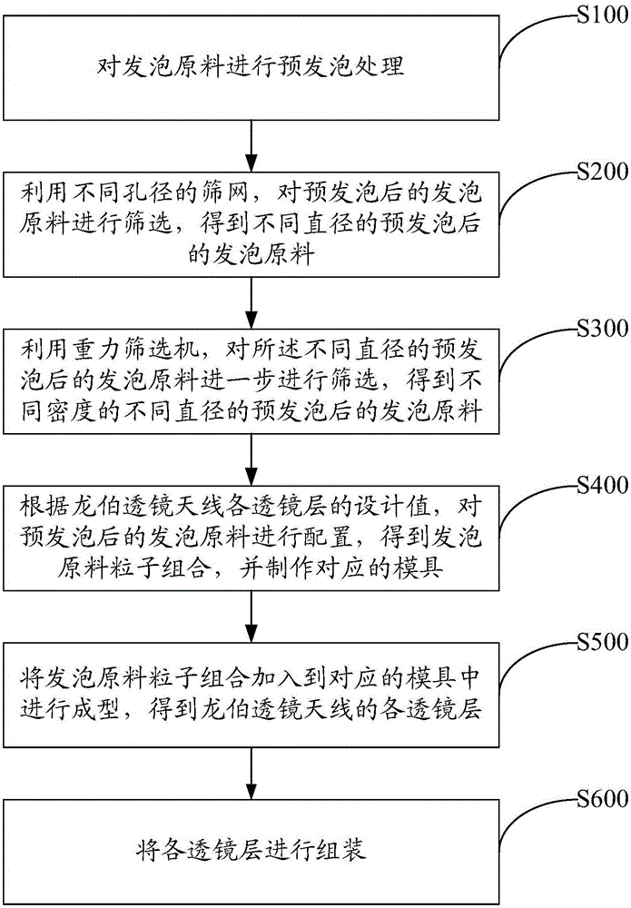
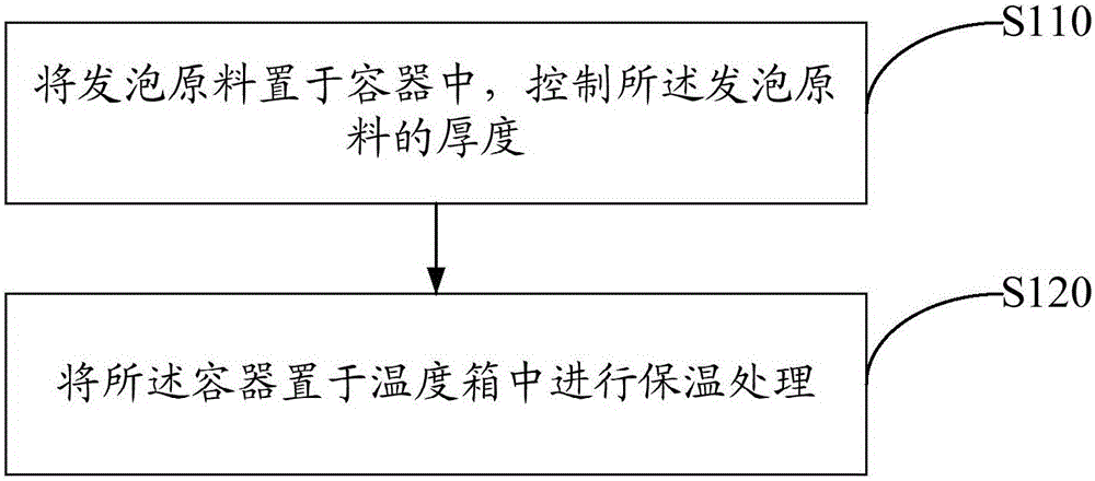
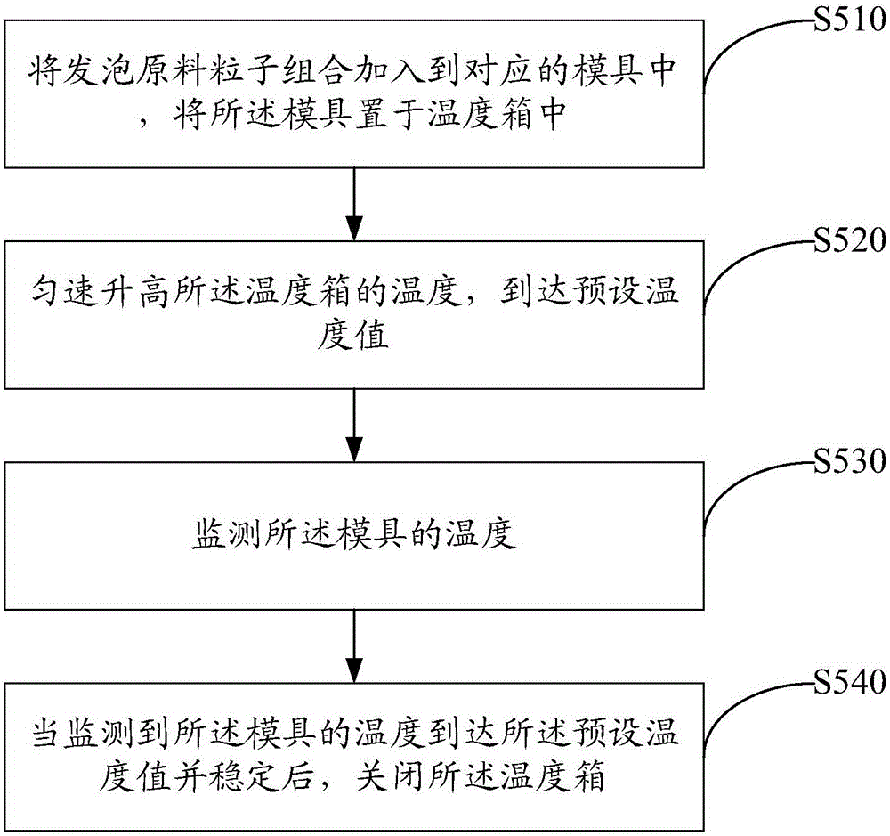
The invention discloses a manufacturing method of a luneberg lens antenna. The method comprises the following steps of carrying out pre-foaming treatment on a foam material; preparing the pre-foamed foam material according to design values of various lens layers of the luneberg lens antenna to obtain foam a material particle composition and manufacturing a corresponding mold; adding the material particle composition to the corresponding mold for molding to obtain the lens layers of the luneberg lens antenna; and assembling the lens layers. According to the technical scheme, the accuracy of dielectric constants of the lens layers of a luneberg lens can be improved; and the change of the dielectric constants of the luneberg lens is closer to the ideal change rule, so that the working performance of the luneberg lens antenna is improved.
Description
technical field [0001] The invention relates to a manufacturing method of a Lunberg lens antenna. Background technique [0002] At present, the Lunberg lens antenna is widely concerned and used by people because of its many characteristics superior to the parabolic antenna. Theoretically, in order to realize the ideal working performance of the Lunberg lens antenna, the dielectric constant of the Lunberg lens, an important component, should change in an ideal law, that is, the dielectric constant changes continuously and smoothly from the core to the outer layer, from 2 to 1. At present, in order to realize the ideal variation of the permittivity of the Lunberg lens, a common method is to use a plurality of lens layers whose diameters gradually change and the permittivity also gradually changes to be stacked concentrically. However, in the production process of the traditional Lunberg lens antenna, the dielectric constant of each lens layer generally has defects that are di...
Claims
Login to View More Application Information
Patent Timeline
 IPC IPC(8): H01Q15/08
Inventor 岑建立
Owner 深圳贝斯特网联通讯设备有限公司