
2P high-speed copper bar rotor low vibration insurance structure

A low-vibration, copper-bar technology, applied in the direction of magnetic circuit rotating parts, magnetic circuit shape/style/structure, electric components, etc., can solve the problems of alarm shutdown, production stoppage, vibration exceeding limit, insufficient reliability, etc., to ensure safety. Operation, reliability enhancement, dynamic stability enhancement effect

Inactive Publication Date: 2016-11-09
WOLONG ELECTRIC GRP CO LTD +1
View PDF5 Cites 2 Cited by
  • Summary
  • Abstract
  • Description
  • Claims
  • Application Information

AI Technical Summary

Problems solved by technology

[0002] The copper bar rotor of the 2P high-speed motor with the conventional design scheme, especially the high-speed copper bar rotor whose outer circle rotation speed exceeds 45m / s, its dynamic stability often cannot meet the low-vibration requirements of the high-speed motor, and the motor cannot leave the factory, even if it is barely Meet the factory standard, because of its insufficient reliability, it is difficult to last, and it shows vibration exceeding the limit under complex load conditions, which leads to alarm shutdown and production shutdown

Method used


Image

  • 2P high-speed copper bar rotor low vibration insurance structure
  • 2P high-speed copper bar rotor low vibration insurance structure
  • 2P high-speed copper bar rotor low vibration insurance structure

Examples


Embodiment 1

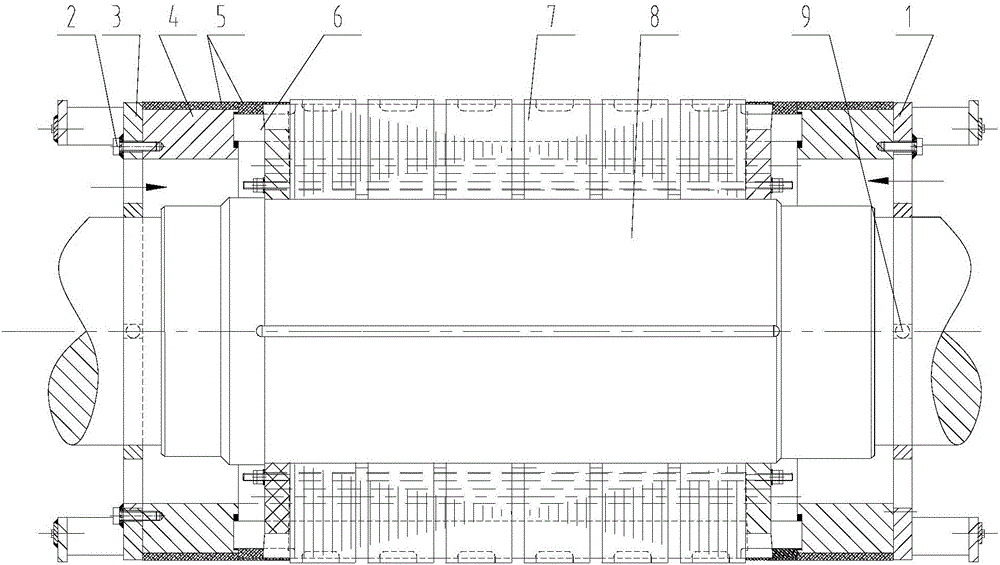
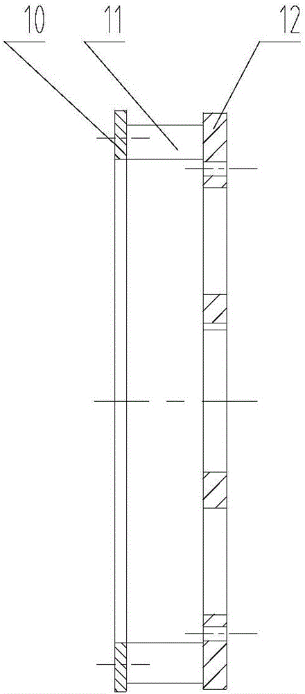
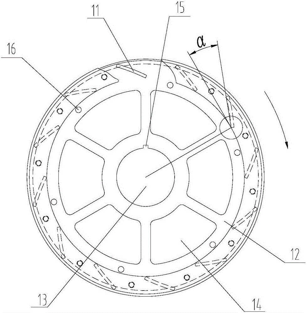
[0027] This embodiment describes a low-vibration safety structure for a 2P high-speed copper bar rotor, such as Figure 1-3 As shown, it includes a copper bar rotor 8. The outer sides of both ends of the copper bar rotor 8 are connected to the left fan 3 and the right fan 1 respectively. The copper bar rotor 8 has a plurality of rotor copper bars 6 inserted in the groove shape, The rotor copper bar 6 penetrates into a rotor iron core 7 and is hammered and tightened in the axial full length of the core part. The two ends of the rotor copper bar 6 are respectively bound by a mesh latitude belt 5 and clamped to one end. Ring 4, the outer end surface of the end ring 4 on the left side of the copper bar rotor 8 is tightly connected to the left fan 3, and the outer end surface of the end ring 4 on the right side of the copper bar rotor 8 is tightly connected to the right fan 1 The left fan 3 and the right fan 1 have the same structure and opposite rotation directions. The left fan 3 ...


PUM


Abstract

A low-vibration insurance structure for a 2P high-speed copper bar rotor, relating to the technical field of high-voltage motor components, in particular a low-vibration insurance structure for a 2P high-speed copper bar rotor, which includes a copper bar rotor, and the left and right ends of the copper bar rotor The left fan and the right fan are respectively connected. The copper bar rotor is provided with a number of rotor copper bars. The rotor copper bars penetrate a rotor iron core and are hammered and tightened axially along the entire length of the iron core. The rotor The two ends of the copper bar are brazed with one end ring respectively, the outer end faces of the two end rings at the left end of the copper bar rotor are fastened to the left fan, and the outer end faces of the two end rings at the right end of the copper bar rotor are fastened to the The right fan, the left fan and the right fan have the same structure and the opposite direction of rotation, the left fan and the right fan all sequentially include a fan plate, fan blades and a fan pressing ring. The invention successfully solves the long-term vibration problem caused by the instability of the 2P high-voltage high-speed copper bar rotor motor under dynamic and thermal conditions during high-speed operation.

Description

Technical field [0001] The invention relates to the technical field of high-voltage motor parts, and in particular to a low-vibration safety structure of a 2P high-speed copper bar rotor. Background technique [0002] Conventional design schemes of copper bar rotors of 2P high-speed motors, especially high-speed copper bar rotors whose outer circumference rotation speed exceeds 45m / s, their dynamic stability often cannot meet the low-vibration requirements of high-speed motors, and the motor cannot be shipped out of the factory, even if reluctantly Reaching the factory standard, it is difficult to last because of its lack of reliability, and under complex load conditions, the vibration exceeds the limit and causes the alarm to stop and stop production. Summary of the invention [0003] The purpose of the present invention is to provide a low-vibration safety structure for a 2P high-speed copper bar rotor in order to solve the above-mentioned technical deficiencies, which can ensu...

Claims


Application Information

Patent Timeline
IPC IPC(8): H02K1/28H02K1/32
CPCH02K1/28H02K1/32H02K9/04
Inventor 吴泰赵代夫程雪玲郭锦州徐汉锐
Owner WOLONG ELECTRIC GRP CO LTD
Learn More