Piezoelectric type fluid power generator

A generator and piezoelectric technology, applied in the direction of generator/motor, piezoelectric effect/electrostrictive or magnetostrictive motor, electrical components, etc., can solve the problem of piezoelectric wafers being fragile, complex in structure and reliability Low-level problems, to achieve the effect of controllable compressive stress range, simple structure and manufacturing process, and high reliability

Inactive Publication Date: 2016-11-09
ZHEJIANG NORMAL UNIVERSITY
View PDF8 Cites 14 Cited by
  • Summary
  • Abstract
  • Description
  • Claims
  • Application Information

AI Technical Summary

Problems solved by technology

However, most of the existing piezoelectric power generation devices for oil and gas pipelines drive the piezoelectric vibrator to generate electricity through the rotation of the fluid turbine. The structure is complex and bulky, and it is not suitable for pipelines with relatively small diameters. Under alternating tension-compression stress, the piezoelectric wafer is easily broken and has low reliability when the tension stress is too large

Method used


Image

  • Piezoelectric type fluid power generator
  • Piezoelectric type fluid power generator
  • Piezoelectric type fluid power generator

Examples


Embodiment Construction

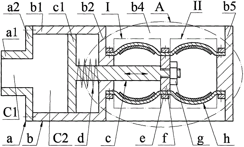
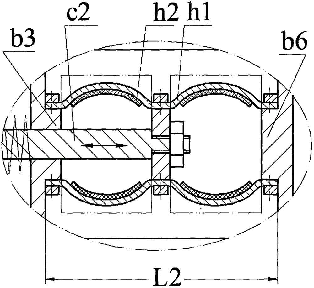
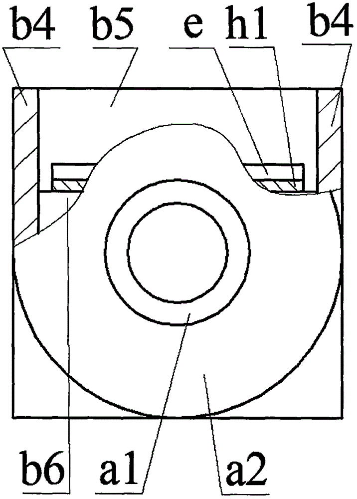
[0011] The left side of the partition b2 of the main body b is provided with a large tube b1, and the right side is provided with two ear plates b4 parallel to each other. The ends of the two ear plates b4 are connected by the side plate b5; the left boss is provided on the partition b2 b3, the side plate b5 is provided with a right boss b6; the cover a2 with the end cover a of the small tube a1 is installed on the end of the large tube b1 through screws and forms two interconnected neck cavities C1 and abdominal cavities C2, the small tube a1 The inner cavity of the tube a1 is the neck cavity C1, and the inner cavity of the large tube b1 is the abdominal cavity C2; the disc body c1 of the vibrator c is placed in the abdominal cavity C2, and the pin shaft c2 of the vibrator c protrudes from the abdominal cavity C2 through the partition b2 , the end of the pin shaft c2 is installed with a connecting plate f through a nut g; the pin shaft c2 is covered with a balance spring d, an...


PUM


Abstract

The invention relates to a piezoelectric type fluid power generator, and belongs to the technical field of piezoelectric power generation. A big cylinder is arranged on the left side of a main body partition plate while two ear plates are arranged on the right side; the end parts of two ear plates are connected by a side plate; a left lug boss and a right lug boss are arranged on the partition plate and the side plate respectively; an end cover plate equipped with a small cylinder is mounted on the end part of the big cylinder; a vibration transmission device plate body is placed in a cavity; a pin shaft extends out of the cavity through the partition plate; a connecting plate is mounted on the end part of the pin shaft; the pin shaft is sleeved with a spring; the two ends of the spring prop against the plate body and the partition plate respectively; piezoelectric vibrators are formed by metal substrates and piezoelectric crystal plates in a gluing manner; and the two ends of the metal substrates of the two piezoelectric vibrators are mounted on the left lug boss and the right lug boss respectively while the middle parts of the metal substrates are mounted on the connecting plate. The piezoelectric type fluid power generator has the characteristics and the advantages as follows: the flat and straight piezoelectric vibrator is mounted with a bending structure to form the power generator which can perform stretching vibration in the length direction of the pipeline; the structure and the process are simple, and the cost is low; the piezoelectric crystal plates only bear the pressure stress within a controllable range, so that high reliability is achieved; and in addition, the electric energy production can be increased easily by increasing the number and prolonging the length of the piezoelectric vibrators.

Description

technical field [0001] The invention belongs to the field of piezoelectric power generation, and in particular relates to a piezoelectric fluid generator for powering an oil and gas pipeline monitoring system. Background technique [0002] Oil and gas pipeline leakage incidents caused by natural corrosion, natural force majeure, especially man-made theft, etc. occur from time to time, not only causing huge economic losses, but also causing serious pollution to the surrounding natural environment. In the past, regular manual inspections were often used to maintain oil and gas pipelines. However, due to the long laying distance and often in inaccessible or inconvenient places, regular inspections are difficult to find leaks and repair them in time. Therefore, various methods have been proposed. Type of pipeline leak detection or anti-theft system. Although some pipeline leakage or anti-theft monitoring and alarm methods proposed are relatively mature at the technical level, t...

Claims


Application Information

Patent Timeline
Patent Type & Authority Applications(China)
IPC IPC(8): H02N2/18
CPCH02N2/185
Inventor 阚君武文欢蔡建程王淑云费凡
Owner ZHEJIANG NORMAL UNIVERSITY
Why Eureka
Try Eureka