Optical fiber interface board system
A fiber optic interface board and series of technologies, applied in the direction of fiber optic transmission, transmission system, electromagnetic wave transmission system, etc., can solve the problem that the rate of data conversion and transmission cannot meet the requirements of fiber optic transmission, limited resources of core devices, unstable working conditions, etc. problem, to achieve the effect of improving data conversion transmission rate, avoiding bus contention or blocking, and low power consumption
- Summary
- Abstract
- Description
- Claims
- Application Information
AI Technical Summary
Problems solved by technology
Method used
Image
Examples
Embodiment 1
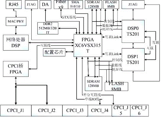
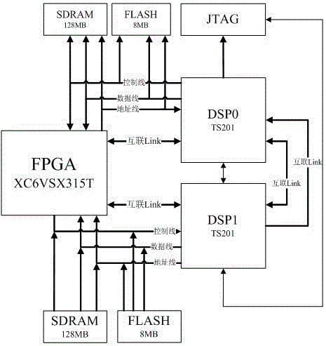
[0028] Such as figure 1 , figure 2 with Figure 4 Shown, a kind of optical fiber interface board system comprises an FPGA chip and an optical module, and FPGA chip is the FPGA chip of the V6 series of Xilinx Company, and the FPGA chip of V6 series connects DSP chip DSP0 and DSP1 by Link port or bus respectively, so The aforementioned DSP0 and DSP1 are interconnected through the Link port, and the V6 series FPGA chip is also connected to the network processor and the CPCI bridge respectively. There is a level conversion chip connected between the network processor and the V6 series FPGA chip, and the optical module is SFP+ package. The optical module communicates with the MGT channel of the V6 series FPGA chip.
[0029] The present invention selects the FPGA chip of the V6 series of Xilinx Company as the core device of data interface management, and this FPGA has integrated 24 road MGT transceiver units, and IO pin quantity is up to 600, and logic resource is abundant, and i...
Embodiment 2
[0033] This embodiment is a further improvement made on the basis of the above embodiments, such as figure 1 with figure 2As shown, in this embodiment, the model of the FPGA chip of the V6 series is XC6VSX315T-FF1156, and the FPGA chip of the V6 series is externally connected with a serial FLASH configuration chip M25P128, which is used for storing codes and self-starting; the external 512M / 32bit DDR2, Used to store cached data; external 16-bit / 100MHz DA chip, the amplitude is +2VPP.
[0034] Both DSP0 and DSP1 are DSP chips of the model ADSP-TS201SYBP-050. The DSP chip of this model has a core clock rate of 500MHz, a bandwidth of 24Mbits embedded DRAM (dynamic random access memory) of 38.4Gbps, 4 average throughput rates, 4. The 8Gbits link port (Linkport) and 14 DMA channels that can realize high-speed and large-capacity data exchange improve the data exchange rate of the present invention. The JTAG signals of DSP0 and DSP1 are led to the front panel of the optical fiber ...
Embodiment 3
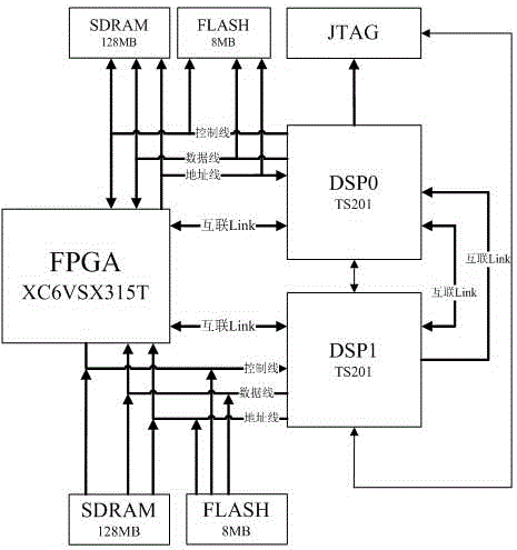
[0036] This embodiment is a further improvement made on the basis of the above embodiments, such as figure 1 , figure 2 and image 3 As shown, in this embodiment, a FLASH chip is connected to the periphery of DSP0 and DSP1 for self-starting after power-on, and a SDRAM chip is connected to the periphery of DSP0 and DSP1, and the clock frequency reaches 50MHz. DSP0 and DSP1 communicate with the Link port or the bus of the FPGA, and the rate is equal to or greater than 150MB / s. Two full-duplex Link ports are seamlessly connected between DSP0 and DSP1, and the rate is greater than 300MB / s. DSP0 and DSP1 connect 32bit data, 13bit address, read and write and other control signals and a full-duplex Link to FPGA to realize Link or bus communication with FPGA, and the rate is not lower than 150MB / s. The model of the FLASH chip is S29GL256P12TFI010, the model of the SDRAM chip is MT48LC32M16, and the peak rate of the DSP chip accessing the SDRAM chip is 480MB / s.
PUM
 Abstract
Description
Claims
Application Information
 - R&D Engineer
- R&D Manager
- IP Professional
- Industry Leading Data Capabilities
- Powerful AI technology
- Patent DNA Extraction
Browse by: Latest US Patents, China's latest patents, Technical Efficacy Thesaurus, Application Domain, Technology Topic, Popular Technical Reports.
© 2024 PatSnap. All rights reserved.Legal|Privacy policy|Modern Slavery Act Transparency Statement|Sitemap|About US| Contact US: help@patsnap.com


